Product Preview DS21Q55
146 of 248 012103
Please contact telecom.support@dalsemi.com or search http://www.maxim-ic.com for updated
information.
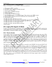
22.4 Receive HDLC Code Example
Below is an example of a receive HDLC routine for controller #1.
1) Reset receive HDLC controller
2) Set HDLC mode, mapping, and high watermark
3) Start new message buffer
4) Enable RPE and RHWM interrupts
5) Wait for interrupt
6) Disable RPE and RHWM interrupts
7) Read HxRPBA register. N = HxRPBA (lower 7 bits are byte count, MSB is status)
8) Read (N AND 7Fh) bytes from receive FIFO and store in message buffer
9) Read INFO5 register
10) If PS2, PS1, PS0 = 000, then go to step 4
11) If PS2, PS1, PS0 = 001, then packet terminated OK, save present message buffer
12) If PS2, PS1, PS0 = 010, then packet terminated with CRC error
13) If PS2, PS1, PS0 = 011, then packet aborted
14) If PS2, PS1, PS0 = 100, then FIFO overflowed
15) Go to step 3
22.5 Legacy FDL Support (T1 Mode)
In order to provide backward compatibility to the older DS21x52 T1 device, the DS21Q55 maintains the
circuitry that existed in the previous generation of the T1 framer. In new applications, it is recommended
that the HDLC controllers and BOC controller are used.
22.5.1 Receive Section
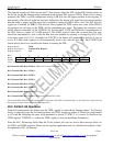
In the receive section, the recovered FDL bits or Fs bits are shifted bit-by-bit into the receive FDL
register (RFDL). Since the RFDL is 8 bits in length, it will fill up every 2ms (8 x 250µs). The framer will
signal an external microcontroller that the buffer has filled via the SR8.3 bit. If enabled via IMR8.3, the
INT pin will toggle low indicating that the buffer has filled and needs to be read. The user has 2ms to
read this data before it is lost. If the byte in the RFDL matches either of the bytes programmed into the
RFDLM1 or RFDLM2 registers, then the SR8.1 bit will be set to a one and the INT pin will toggled low
if enabled via IMR8.1. This feature allows an external microcontroller to ignore the FDL or Fs pattern
until an important event occurs.
The framer also contains a zero destuffer, which is controlled via the T1RCR2.3 bit. In both ANSI T1.403
and TR54016, communications on the FDL follows a subset of a LAPD protocol. The LAPD protocol
states that no more than five ones should be transmitted in a row so that the data does not resemble an
opening or closing flag (01111110) or an abort signal (11111111). If enabled via T1RCR2.3, the device
will automatically look for five ones in a row, followed by a zero. If it finds such a pattern, it will
automatically remove the zero. If the zero destuffer sees six or more ones in a row followed by a zero, the
zero is not removed. The T1RCR2.3 bit should always be set to a one when the device is extracting the
FDL. More on how to use the DS21Q55 in FDL applications in this legacy support mode is covered in a
separate application note.


