


Product Preview DS21Q55
156 of 248 012103
Please contact telecom.support@dalsemi.com or search http://www.maxim-ic.com for updated
information.
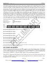
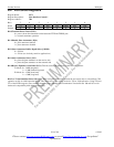
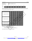
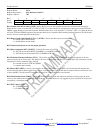
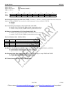
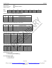
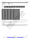
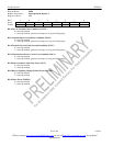
Register Name: TLBC
Register Description: Transmit Line Build-Out Control
Register Address: 7Dh
Bit # 7 6 5 4 3 2 1 0
Name - AGCE GC5 GC4 GC3 GC2 GC1 GC0
Default 0 0 0 0 0 0 0 0
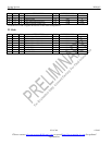
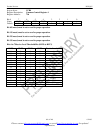
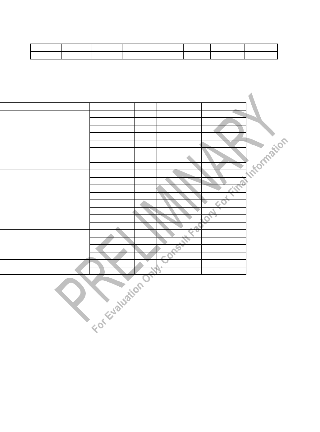
Bit 0–5 Gain Control Bits 0–5 (GC0–GC5). The GC0 through GC5 bits control the gain setting for the nonautomatic gain
mode. Use the tables below for setting the recommended values. The LB (line build-out) column refers to the value in the
L0–L2 bits in LIC1 (Line Interface Control 1) register.
NETWORK MODE LB GC5 GC4 GC3 GC2 GC1 GC0
0 1 0 0 1 1 0
1 0 1 1 0 1 1
2 0 1 1 0 1 0
3 1 0 0 0 0 0
4 1 0 0 1 1 1
5 1 0 0 1 1 1
6 0 1 0 0 1 1
T1, Impedance Match Off
7 1 1 1 1 1 1
0 0 1 1 1 1 0
1 0 1 0 1 0 1
2 0 1 0 1 0 1
3 0 1 1 0 1 0
4 1 0 0 0 1 0
5 1 0 0 0 0 0
6 0 0 1 1 0 0
T1, Impedance Match On
7 1 1 1 1 1 1
0 1 0 0 0 0 1
1 1 0 0 0 0 1
4 1 0 1 0 1 0
E1, Impedance Match Off
5 1 0 1 0 0 0
1 0 1 1 0 1 0
E1, Impedance Match On
2 0 1 1 0 1 0
Bit 6/Automatic Gain Control Enable (AGCE).
0 = use Transmit AGC, TLBC bits 0–5 are “don’t care”
1 = do not use Transmit AGC, TLBC bits 0–5 set nominal level
Bit 7/Unused, must be set to zero for proper operation.