


Product Preview DS21Q55
203 of 248 012103
Please contact telecom.support@dalsemi.com or search http://www.maxim-ic.com for updated
information.
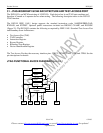
31.1 Instruction Register
The instruction register contains a shift register as well as a latched parallel output and is 3 bits in length.
When the TAP controller enters the shift-IR state, the instruction shift register will be connected between
JTDI and JTDO. While in the shift-IR state, a rising edge on JTCLK with JTMS LOW will shift the data
one stage towards the serial output at JTDO. A rising edge on JTCLK in the exit1-IR state or the exit2-IR
state with JTMS HIGH will move the controller to the update-IR state. The falling edge of that same
JTCLK will latch the data in the instruction shift register to the instruction parallel output. Instructions
supported by the DS2155 and its respective operational binary codes are shown in Table 34-1.
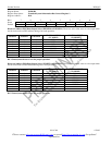
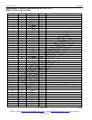
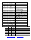
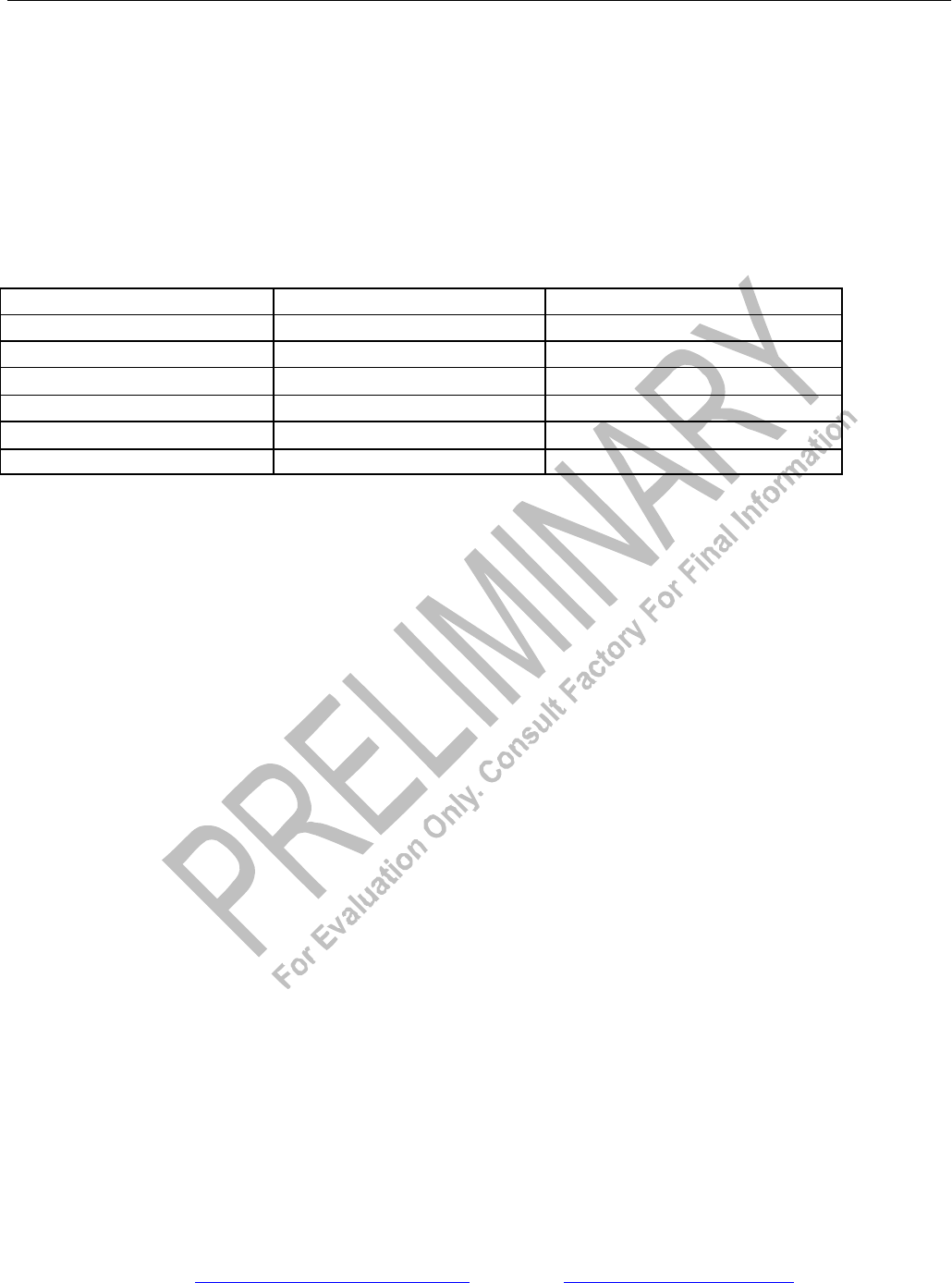
INSTRUCTION CODES FOR IEEE 1149.1 ARCHITECTURE Table 34-1
INSTRUCTION SELECTED REGISTER INSTRUCTION CODES
SAMPLE/PRELOAD Boundary Scan 010
BYPASS Bypass 111
EXTEST Boundary Scan 000
CLAMP Bypass 011
HIGH-Z Bypass 100
IDCODE Device Identification 001