


Product Preview DS21Q55
188 of 248 012103
Please contact telecom.support@dalsemi.com or search http://www.maxim-ic.com for updated
information.
26.1 Number Of Error Registers
The number of error registers determine how many errors will be generated. Up to 1023 errors can be
generated. The host will load the number of errors to be generated into the NOE1 and NOE2 registers.
The host can also update the number of errors to be created by first loading the prescribed value into the
NOE registers and then toggling the WNOE bit in the error rate control registers.
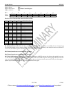
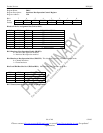
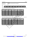
ERROR INSERTION EXAMPLES Table 28-2
VALUE
WRITE READ
000h Do not create any errors No errors left to be inserted
001h Create a single error One error left to be inserted
002h Create two errors Two errors left to be inserted
3FFh Create 1023 errors 1023 errors left to be inserted
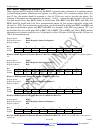
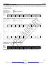
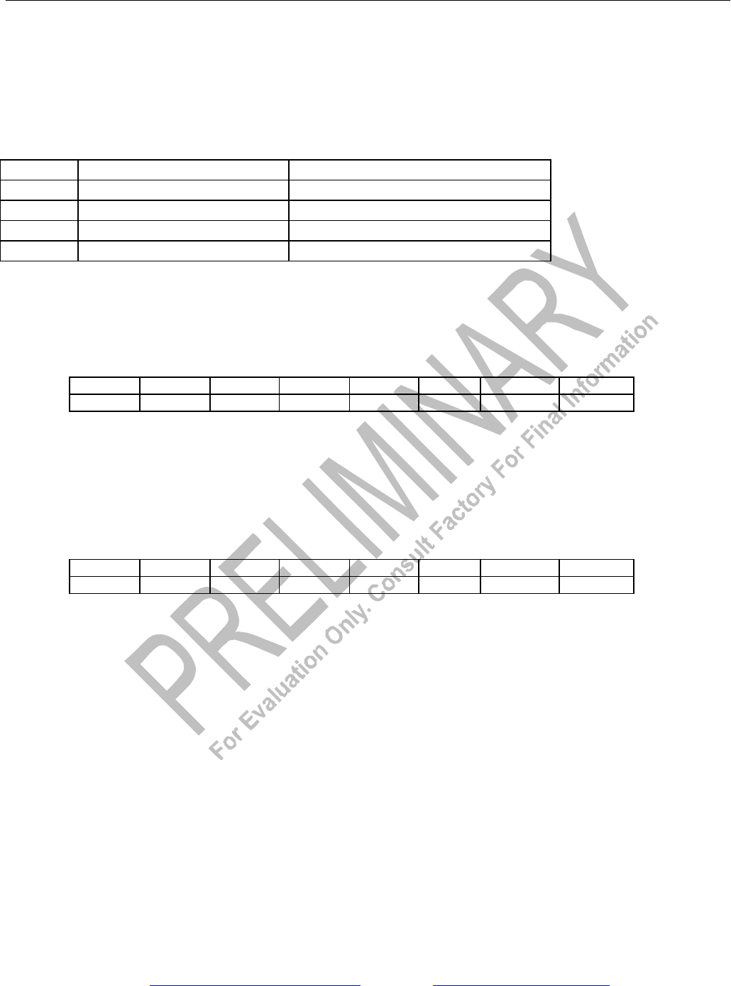
Register Name: NOE1
Register Description: Number Of Errors 1
Register Address: ECh
Bit # 7 6 5 4 3 2 1 0
Name C7 C6 C5 C4 C3 C2 C1 C0
Default 0 0 0 0 0 0 0 0
Bits 0 to 7/Number of Errors Counter Bits 0 to 7 (C0 to C7). Bit C0 is the LSB of the 10-bit counter.
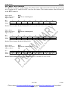
Register Name: NOE2
Register Description: Number Of Errors 2
Register Address: EDh
Bit # 7 6 5 4 3 2 1 0
Name - - - - - - C9 C8
Default 0 0 0 0 0 0 0 0
Bits 0 to 1/Number of Errors Counter Bits 8 to 9 (C8 to C9). Bit C9 is the MSB of the 10-bit counter.