


Product Preview DS21Q55
93 of 248 012103
Please contact telecom.support@dalsemi.com or search http://www.maxim-ic.com for updated
information.
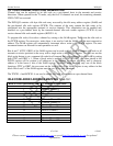
15.2.2 Software Signaling Insertion Enable Registers, E1 CAS Mode
In E1 CAS mode, the CAS signaling alignment/alarm byte can be sourced from the transmit signaling
registers along with the signaling data.
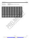
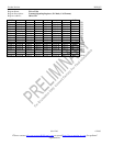
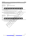
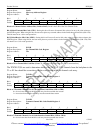
Register Name: SSIE1
Register Description: Software Signaling Insertion Enable 1
Register Address: 08h
Bit # 7 6 5 4 3 2 1 0
Name CH7 CH6 CH5 CH4 CH3 CH2 CH1 UCAW
Default 0 0 0 0 0 0 0 0
Bit 0/Upper CAS Align/Alarm Word (UCAW). Selects the upper CAS align/alarm pattern (0000) to be sourced from the
upper 4 bits of the TS1 register.
0 = do not source the upper CAS align/alarm pattern from the TS1 register
1 = source the upper CAS align/alarm pattern from the TS1 register
Bits 1 to 7/Software Signaling Insertion Enable for Channels 1 to 7 (CH1 to CH7 ). These bits determine which channels
are to have signaling inserted form the Transmit Signaling registers.
0 = do not source signaling data from the TSx registers for this channel
1 = source signaling data from the TSx registers for this channel
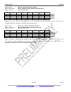
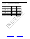
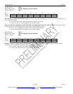
Register Name: SSIE2
Register Description: Software Signaling Insertion Enable 2
Register Address: 09h
Bit # 7 6 5 4 3 2 1 0
Name CH15 CH14 CH13 CH12 CH11 CH10 CH9 CH8
Default 0 0 0 0 0 0 0 0
Bits 0 to 7/Software Signaling Insertion Enable for Channels 8 to 15 (CH8 to CH15). These bits determine which channels
are to have signaling inserted form the transmit signaling registers.
0 = do not source signaling data from the TS registers for this channel
1 = source signaling data from the TS registers for this channel