


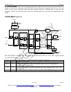
Product Preview DS21Q55
41 of 248 012103
Please contact telecom.support@dalsemi.com or search http://www.maxim-ic.com for updated
information.
marked as “double interrupt bits.” An interrupt will be produced when the condition occurs and when it
clears.
6.4 Information Registers
Information registers operate the same as status registers except they cannot cause interrupts. They are all
latched except for INFO7 and some of the bits in INFO5 and INFO6. INFO7 register is a read only
register and it reports the status of the E1 synchronizer in real time. INFO7 and some of the bits in INFO6
and INFO5 are not latched and it is not necessary to precede a read of these bits with a write.
6.5 Interrupt Information Registers
The Interrupt Information Registers provide an indication of which Status Registers (SR1 through SR9)
are generating an interrupt. When an interrupt occurs, the host can read IIR1 and IIR2 to quickly identify
which of the 9 status registers are causing the interrupt.
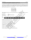
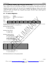
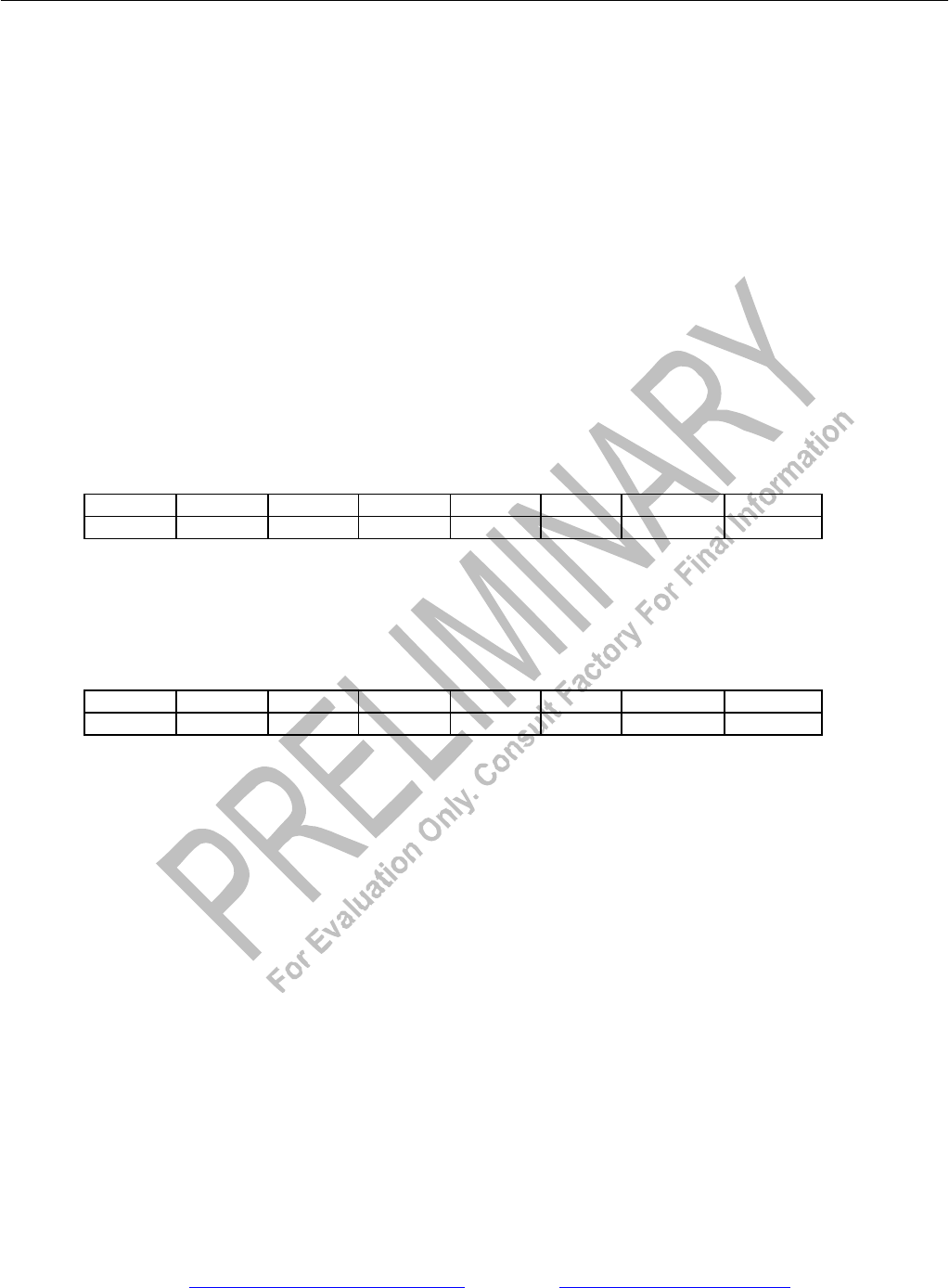
Register Name: IIR1
Register Description: Interrupt Information Register 1
Register Address: 14h
Bit # 7 6 5 4 3 2 1 0
Name SR8 SR7 SR6 SR5 SR4 SR3 SR2 SR1
Default 0 0 0 0 0 0 0 0
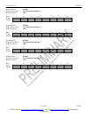
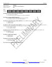
Register Name: IIR2
Register Description: Interrupt Information Register 2
Register Address: 15h
Bit # 7 6 5 4 3 2 1 0
Name - - - - - - - SR9
Default 0 0 0 0 0 0 0 0