


Product Preview DS21Q55
83 of 248 012103
Please contact telecom.support@dalsemi.com or search http://www.maxim-ic.com for updated
information.
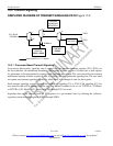
registers for T1 mode and PCDR1-PCDR4 registers for E1 mode. In E1 mode, the user will generally
select all channels when doing reinsertion.
15.1.2.2 Force Receive Signaling All Ones
In T1 mode, the user can, on a per-channel basis, force the robbed-bit signaling-bit positions to a one.
This is done by using the per-channel register, which is described in the Special Per-Channel Operation
section. The user sets the BTCS bit in the PCPR register. The channels that are to be forced to one are
selected by writing to the PCDR1-PCDR3 registers.
15.1.2.3 Receive-Signaling Freeze
The signaling data in the four-multiframe signaling buffer will be frozen in a known good state upon
either a loss of synchronization (OOF event), carrier loss, or frame slip. This action meets the
requirements of BellCore TR–TSY–000170 for signaling freezing. To allow this freeze action to occur,
the RFE control bit (SIGCR.4) should be set high. The user can force a freeze by setting the RFF control
bit (SIGCR.3) high. The RSIGF output pin provides a hardware indication that a freeze is in effect. The
four multiframe buffer provides a three-multiframe delay in the signaling bits provided at the RSIG pin
(and at the RSER pin if receive signaling reinsertion is enabled). When freezing is enabled (RFE = 1), the
signaling data will be held in the last known good state until the corrupting error condition subsides.
When the error condition subsides, the signaling data will be held in the old state for at least an additional
9ms (or 4.5ms in D4 framing mode) before being allowed to be updated with new signaling data.
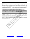
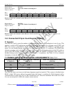
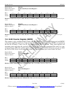
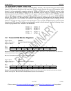
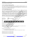
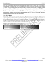
Register Name: SIGCR
Register Description: Signaling Control Register
Register Address: 40h
Bit # 7 6 5 4 3 2 1 0
Name - - - RFE RFF - - -
Default 0 0 0 0 0 0 0 0
Bit 0/Unused, must be set to zero for proper operation.
Bit 1/Unused, must be set to zero for proper operation.
Bit 2/Unused, must be set to zero for proper operation.
Bit 3/Receive Force Freeze (RFF). Freezes receive-side signaling at RSIG (and RSER if receive signaling reinsertion is
enabled); will override receive-freeze enable (RFE). See Receive Signaling Freeze.
0 = do not force a freeze event
1 = force a freeze event
Bit 4/Receive Freeze Enable (RFE). See Receive Signaling Freeze.
0 = no freezing of receive signaling data will occur
1 = allow freezing of receive signaling data at RSIG (and RSER if receive signaling reinsertion is enabled).
Bit 5/Unused, must be set to zero for proper operation.
Bit 6/Unused, must be set to zero for proper operation.
Bit 7/Unused, must be set to zero for proper operation.