


Product Preview DS21Q55
199 of 248 012103
Please contact telecom.support@dalsemi.com or search http://www.maxim-ic.com for updated
information.
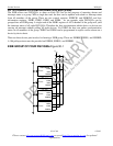
31. JTAG-BOUNDARY-SCAN ARCHITECTURE AND TEST-ACCESS PORT
The DS21Q55 is an MCM consisting of 4 DS2155s. Each device has its on JTAG state machine and
therefore is treated as 4 separate devices when testing. The following description refers to the DS2155
JTAG function.
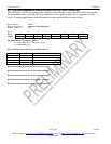
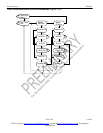
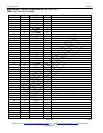
The DS2155 IEEE 1149.1 design supports the standard instruction codes SAMPLE/PRELOAD,
BYPASS, and EXTEST. Optional public instructions included are HIGH-Z, CLAMP, and IDCODE
(Figure 21). The DS21Q55 contains the following as required by IEEE 1149.1 Standard Test-Access Port
and Boundary-Scan Architecture:
§ Test Access Port (TAP)
§ TAP Controller
§ Instruction Register
§ Bypass Register
§ Boundary Scan Register
§ Device Identification Register
The Test Access Port has the necessary interface pins: JTRST, JTCLK, JTMS, JTDI, and JTDO. See the
pin descriptions for details.
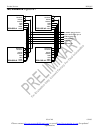
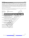
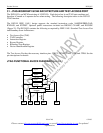
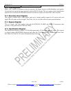
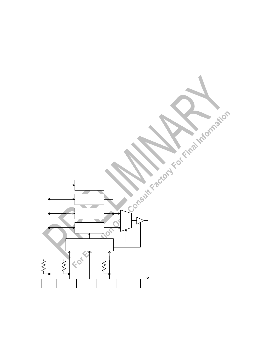
JTAG FUNCTIONAL BLOCK DIAGRAM Figure 34-1
+V
Boundary Scan
Register
Identification
Register
Bypass
Register
Instruction
Register
JTDI
JTMS
JTCLK
JTRST
JTDO
+V
+V
Test Access Port
Controller
MUX
10k
10k
10k
Select
Output Enable