


Product Preview DS21Q55
68 of 248 012103
Please contact telecom.support@dalsemi.com or search http://www.maxim-ic.com for updated
information.
12. LOOPBACK CONFIGURATION
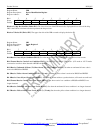
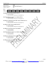
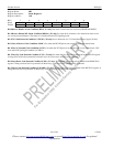
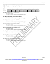
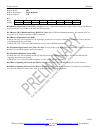
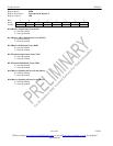
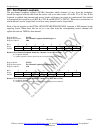
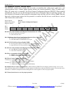
Register Name: LBCR
Register Description: Loopback Control Register
Register Address: 4Ah
Bit # 7 6 5 4 3 2 1 0
Name - - - LIUC LLB RLB PLB FLB
Default 0 0 0 0 0 0 0 0
Bit 0/Framer Loopback (FLB).
0 = loopback disabled
1 = loopback enabled
This loopback is useful in testing and debugging applications. In FLB, the device will loop data from the transmit side back to
the receive side. When FLB is enabled, the following will occur:
1) T1 Mode: An unframed all ones code will be transmitted at TPOSO and TNEGO.
E1 Mode: Normal data will be transmitted at TPOSO and TNEGO.
2) Data at RPOSI and RNEGI will be ignored.
3) All receive side signals will take on timing synchronous with TCLK instead of RCLKI.
4) Please note that it is not acceptable to have RCLK tied to TCLK during this loopback because this will cause an unstable
condition.
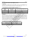
Bit 1/Payload Loopback (PLB).
0 = loopback disabled
1 = loopback enabled
When PLB is enabled, the following will occur:
1) Data will be transmitted from the TPOSO and TNEGO pins synchronous with RCLK instead of TCLK.
2) All of the receive side signals will continue to operate normally.
3) The TCHCLK and TCHBLK signals are forced low.
4) Data at the TSER and TSIG pins is ignored.
5) The TLCLK signal will become synchronous with RCLK instead of TCLK.
T1 Mode: Normally, this loopback is only enabled when ESF framing is being performed but can be enabled also in D4
framing applications. In a PLB situation, the device will loop the 192 bits of pay-load data (with BPVs corrected) from the
receive section back to the transmit section. The FPS framing pattern, CRC6 calculation, and the FDL bits are not looped back,
they are reinserted by the device.
E1 Mode: In a PLB situation, the device will loop the 248 bits of payload data (with BPVs corrected) from the receive section
back to the transmit section. The transmit section will modify the payload as if it was input at TSER. The FAS word, Si, Sa
and E bits, and CRC4 are not looped back, they are reinserted by the device.
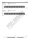
Bit 2/Remote Loopback (RLB). In this loopback, data input via the RPOSI and RNEGI pins will be transmitted back to the
TPOSO and TNEGO pins. Data will continue to pass through the receive side framer of the device as it would normally and
the data from the transmit side formatter will be ignored.
0 = loopback disabled
1 = loopback enabled