


Product Preview DS21Q55
57 of 248 012103
Please contact telecom.support@dalsemi.com or search http://www.maxim-ic.com for updated
information.
9.3 E1 Information Registers
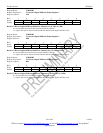
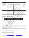
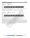
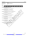
Register Name: INFO3
Register Description: Information Register 3
Register Address: 12h
Bit # 7 6 5 4 3 2 1 0
Name - - - - - CRCRC FASRC CASRC
Default 0 0 0 0 0 0 0 0
Bit 0/CAS Resync Criteria Met Event (CASRC). Set when two consecutive CAS MF alignment words are received in error.
Bit 1/FAS Resync Criteria Me t Event (FASRC. Set when three consecutive FAS words are received in error.
Bit 2/CRC Resync Criteria Met Event (CRCRC). Set when 915/1000 code words are received in error.
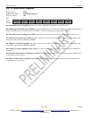
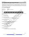
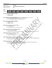
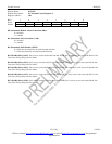
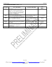
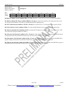
Register Name: INFO7
Register Description: Information Register 7 (Real Time)
Register Address: 30h
Bit # 7 6 5 4 3 2 1 0
Name CSC5 CSC4 CSC3 CSC2 CSC0 FASSA CASSA CRC4SA
Default 0 0 0 0 0 0 0 0
Bit 0/CRC4 MF Sync Active (CRC4SA). Set while the synchronizer is searching for the CRC4 MF alignment word.
Bit 1/CAS MF Sync Active (CASSA). Set while the synchronizer is searching for the CAS MF alignment word.
Bit 2/FAS Sync Active (FASSA). Set while the synchronizer is searching for alignment at the FAS level.
Bit 3 to 7/CRC4 Sync Counter Bits (CSC0 and CSC2 to CSC4). The CRC4 sync counter increments each time the 8ms -
CRC4 multiframe search times out. The counter is cleared when the framer has successfully obtained synchronization at the
CRC4 level. The counter can also be cleared by disabling the CRC4 mode (E1RCR1.3 = 0). This counter is useful for
determining the amount of time the framer has been searching for synchronization at the CRC4 level. ITU G.706 suggests that
if synchronization at the CRC4 level cannot be obtained within 400ms, then the search should be abandoned and proper action
taken. The CRC4 sync counter will rollover. CSC0 is the LSB of the 6-bit counter. (Note: The second LSB, CSC1, is not
accessible. CSC1 is omitted to allow resolution to >400ms using 5 bits.)