


Product Preview DS21Q55
69 of 248 012103
Please contact telecom.support@dalsemi.com or search http://www.maxim-ic.com for updated
information.
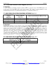
Bit 3/Local Loopback (LLB). In this loopback, data will continue to be transmitted as normal through the transmit side of the
device. Data being received at RTIP and RRING will be replaced with the data being transmitted. Data in this loopback will
pass through the jitter attenuator. (See Figure 1-1 Line Interface Unit.)
0 = loopback disabled
1 = loopback enabled
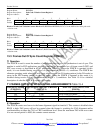
Bit 4/Line Interface Unit Mux Control (LIUC). This is a software version of the LIUC pin. When the LIUC pin is connected
high the LIUC bit has control. When the LIUC pin is connected low the framer and LIU are separated and the LIUC bit has no
effect.
0 = if LIUC pin connected high, LIU internally connected to framer block and deactivate the
TPOSI/TNEGI/TCLKI/RPOSI/RNEGI/RCLKI pins.
1 = if LIUC pin connected high, disconnect LIU from framer block and activate the
TPOSI/TNEGI/TCLKI/RPOSI/RNEGI/RCLKI pins.
LIUC pin LIUC bit
0 0 LIU and Framer Separated
0 1 LIU and Framer Separated
1 0 LIU and Framer Connected
1 1 LIU and Framer Separated
Bit 5/Unused, must be set to zero for proper operation.
Bit 6/Unused, must be set to zero for proper operation.
Bit 7/Unused, must be set to zero for proper operation.