


Product Preview DS21Q55
165 of 248 012103
Please contact telecom.support@dalsemi.com or search http://www.maxim-ic.com for updated
information.
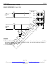
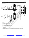
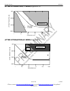
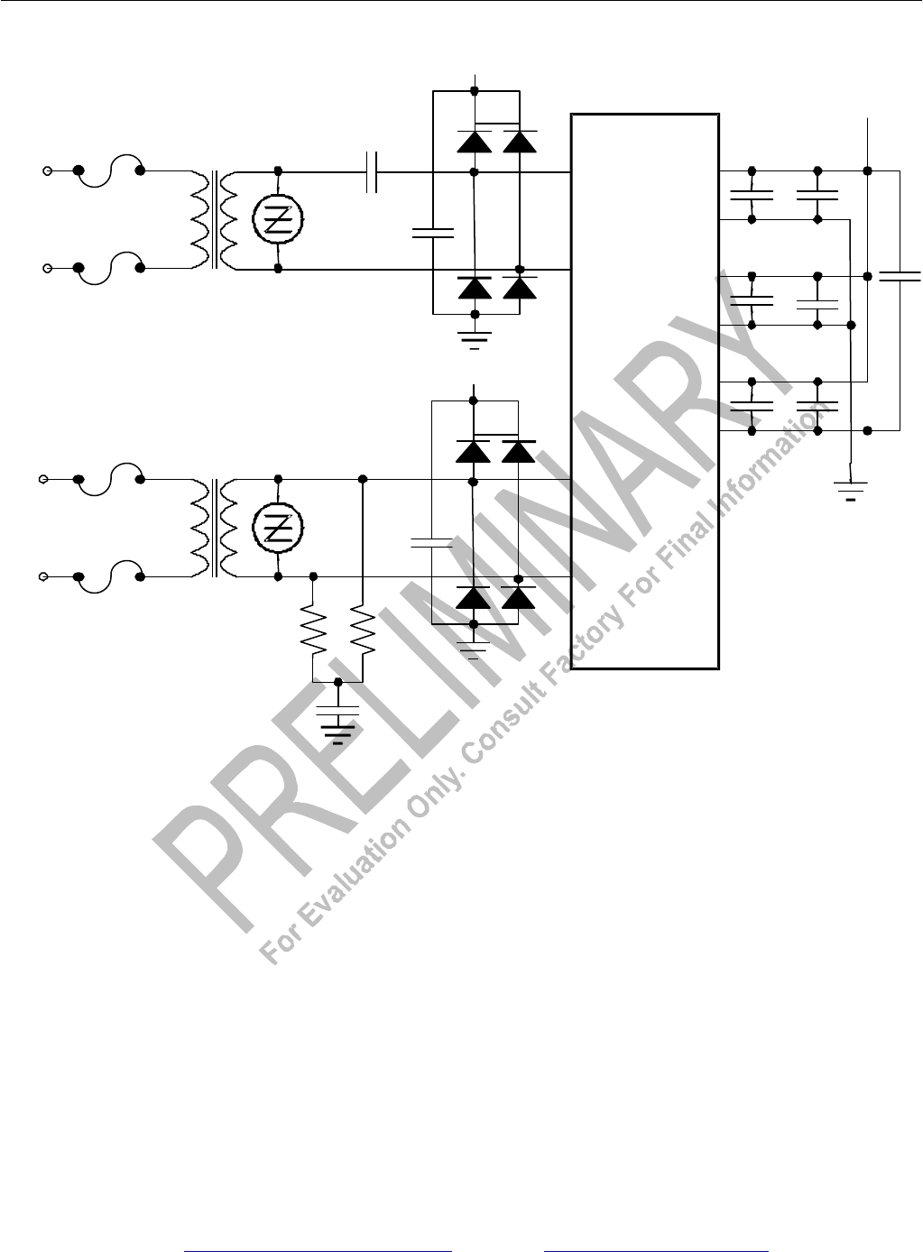
PROTECTED INTERFACE USING INTERNAL RECEIVE TERMINATION
Figure 25-5
NOTES:
1) All resistor values are ±1%.
2) X1 and X2 are very low DCR transformers
3) C1 = 1µF ceramic.
4) S1 and S2 are 6V transient suppressers.
5) D1 to D8 are Schottky diodes.
6) The fuses, F1–F4, are optional to prevent AC power-line crosses from compromising the
transformers.
7) The 68µF is used to keep the local power-plane potential within tolerance during a surge.
TTIP
TRING
RTIP
RRING
DV
DD
TV
DD
RV
DD
V
DD
V
DD
DV
SS
TV
S
S
RV
SS
DS21Q55
68µF
2:1
1:1
D1
D2
D3
D4
C1
F1
F2
F3
F4
S1
0.1µF
0.1µF
0.1µF
.01µF
X1
X2
TRANSMIT
LINE
RECEIV
E
LINE
0.1µF
10µF
10µF
+
+
+
0.1µF
S2
60
60
V
DD
D5
D6
D7
D8
0.1µF