


Product Preview DS21Q55
195 of 248 012103
Please contact telecom.support@dalsemi.com or search http://www.maxim-ic.com for updated
information.
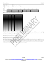
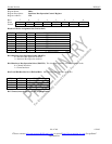
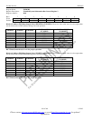
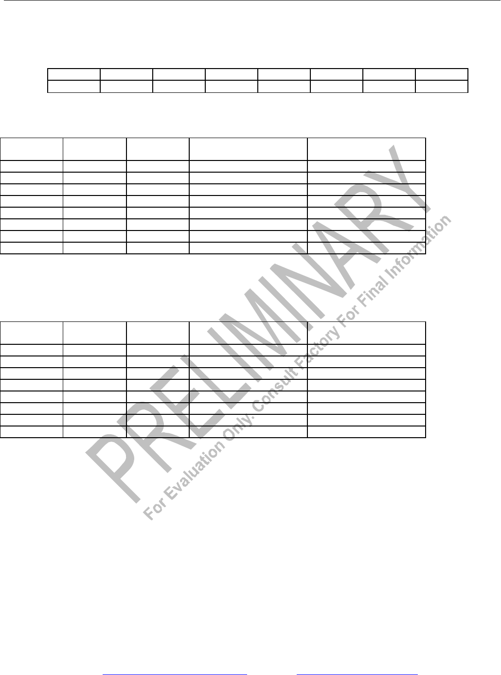
Register Name: ESIBCR2
Register Description: Extended System Information Bus Control Register 2
Register Address: B1h
Bit # 7 6 5 4 3 2 1 0
Name - ESI4SEL2
ESI4SEL1
ESI4SEL0
- ESI3SEL2
ESI3SEL1
ESI3SEL0
Default 0 0 0 0 0 0 0 0
Bits 0 to 2/Address ESI3 Data Output Select (ESI3SEL0 to ESI3SEL2). These bits select what status is to be output when
the device decodes an ESI3 address during a bus read operation.
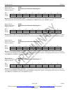
ESI3SEL2 ESI3SEL1 ESI3SEL0
STATUS OUTPUT
(T1 MODE)
STATUS OUTPUT
(E1 MODE)
0 0 0 RBL RUA1
0 0 1 RYEL RRA
0 1 0 LUP RDMA
0 1 1 LDN V52LNK
1 0 0 SIGCHG SIGCHG
1 0 1 ESSLIP ESSLIP
1 1 0 - -
1 1 1 - -
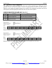
Bit 3/Unused, must be set to zero for proper operation.
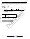
Bits 4 to 6/Address ESI4 Data Output Select (ESI4SEL0 to ESI4SEL2). These bits select what status is to be output when
the device decodes an ESI4 address during a bus-read operation.
ESI4SEL2 ESI4SEL1 ESI4SEL0
STATUS OUTPUT
(T1 MODE)
STATUS OUTPUT
(E1 MODE)
0 0 0 RBL RUA1
0 0 1 RYEL RRA
0 1 0 LUP RDMA
0 1 1 LDN V52LNK
1 0 0 SIGCHG SIGCHG
1 0 1 ESSLIP ESSLIP
1 1 0 - -
1 1 1 - -
Bit 7/Unused, must be set to zero for proper operation.