


Product Preview DS21Q55
99 of 248 012103
Please contact telecom.support@dalsemi.com or search http://www.maxim-ic.com for updated
information.
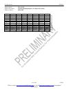
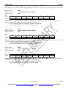
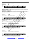
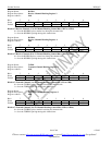
Register Name: IAAR
Register Description: Idle Array Address Register
Register Address: 7Eh
Bit # 7 6 5 4 3 2 1 0
Name GRIC GTIC IAA5 IAA4 IAA3 IAA2 IAA1 IAA0
Default 0 0 0 0 0 0 0 0
Bits 0 to 5/Channel Pointer Address Bits (IAA0 to IAA5). IAA0 is the LSB of the 5-bit Channel Code.
Bit 6/Global Transmit Idle Code (GTIC). Setting this bit will cause all transmit idle codes to be set to the value written to
the PCICR register. When using this bit, the user must place any transmit address in the IAA0 through IAA5 bits (00h–1Fh).
This bit must be set = 0 for read operations.
Bit 7/Global Receive Idle Code (GRIC). Setting this bit will cause all receive idle codes to be set to the value written to the
PCICR register. When using this bit, the user must place any receive address in the IAA0 through IAA5 bits (20h–3Fh). This
bit must be set = 0 for read operations.
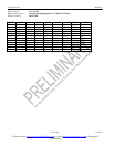
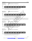
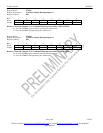
Register Name: PCICR
Register Description: Per-Channel Idle Code Register
Register Address: 7Fh
Bit # 7 6 5 4 3 2 1 0
Name C7 C6 C5 C4 C3 C2 C1 C0
Default 0 0 0 0 0 0 0 0
Bits 0 to 7/Per-Channel Idle Code Bits (C0 to C7). C0 is the LSB of the code (this bit is transmitted last).
The TCICE1/2/3/4 are used to determine which of the 24 T1 or 32 E1 channels from the backplane to the
T1 or E1 line should be overwritten with the code placed in the per-channel code array.
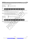
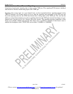
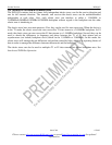
Register Name: TCICE1
Register Description: Transmit Channel Idle Code Enable Register 1
Register Address: 80h
Bit # 7 6 5 4 3 2 1 0
Name CH8 CH7 CH6 CH5 CH4 CH3 CH2 CH1
Default 0 0 0 0 0 0 0 0
Bits 0 to 7/Transmit Channels 1 to 8 Code Insertion Control Bits (CH1 to CH8).
0 = do not insert data from the idle code array into the transmit data stream
1 = insert data from the idle code array into the transmit data stream
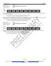
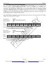
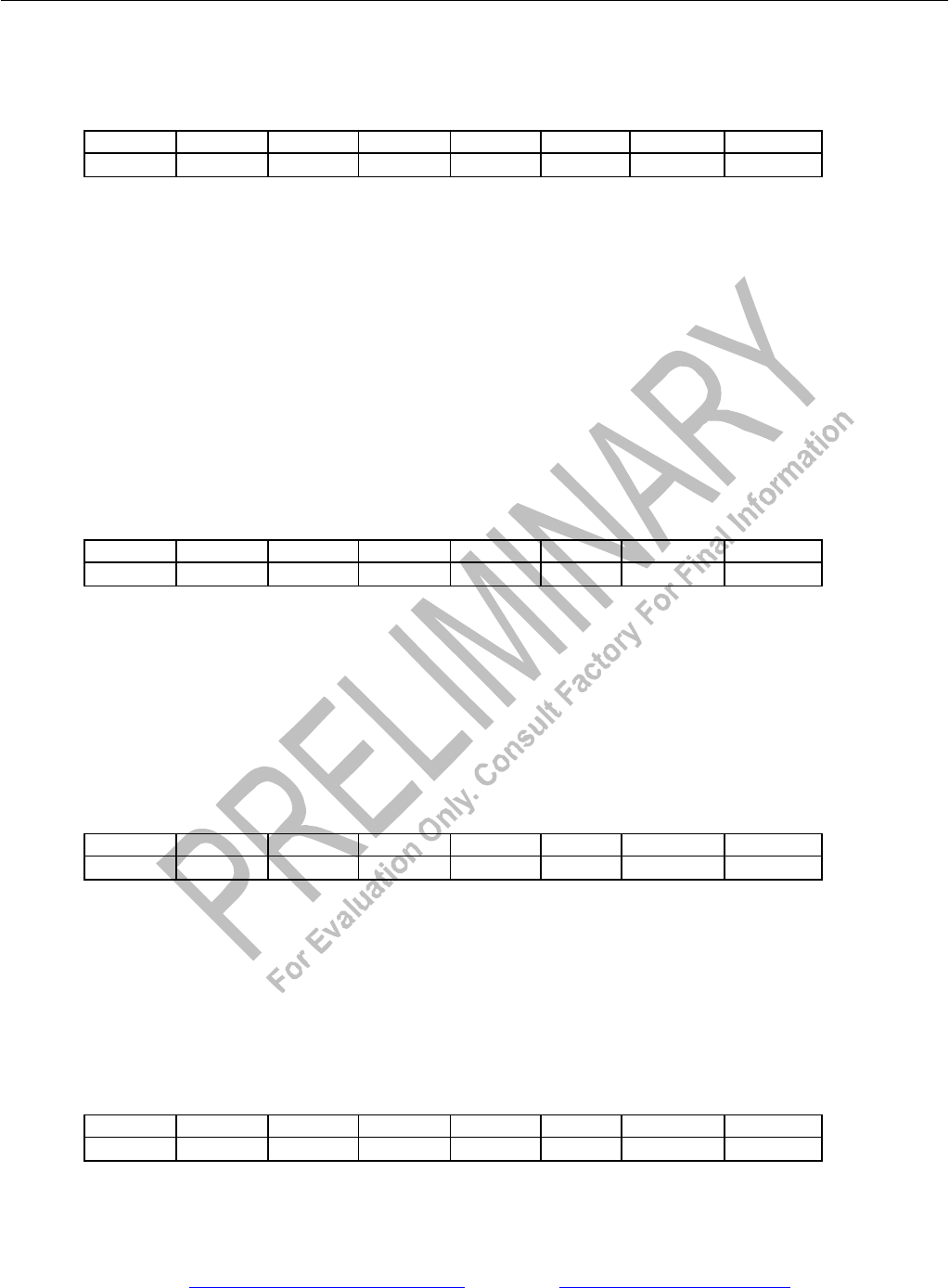
Register Name: TCICE2
Register Description: Transmit Channel Idle Code Enable Register 2
Register Address: 81h
Bit # 7 6 5 4 3 2 1 0
Name CH16 CH15 CH14 CH13 CH12 CH11 CH10 CH9
Default 0 0 0 0 0 0 0 0
Bits 0 to 7/Transmit Channels 9 to 16 Code Insertion Control Bits (CH9 to CH16).
0 = do not insert data from the idle code array into the transmit data stream