


Product Preview DS21Q55
149 of 248 012103
Please contact telecom.support@dalsemi.com or search http://www.maxim-ic.com for updated
information.
23. LINE INTERFACE UNIT (LIU)
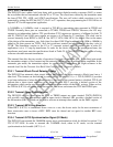
The LIU in the DS21Q55 contains three sections: the receiver, which handles clock and data recovery;
the transmitter, which wave-shapes and drives the network line; and the jitter attenuator. These three
sections are controlled by the line interface control registers (LIC1–LIC4), which are described below.
The LIU has its own T1/E1 mode select bit and can operate independently of the framer function.
The DS21Q55 can switch between T1 or E1 networks without changing any external components on
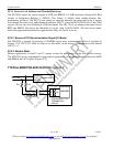
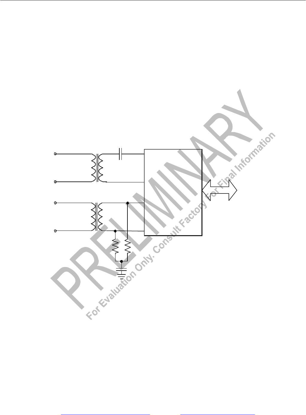
either the transmit or receive side. Figure 25-1 shows a network connection using minimal components.
In this configuration the device can connect to T1, J1, or E1 (75O or 120O) without any component
change. The receiver can adjust the 120O termination to 100O or 75O. The transmitter can adjust its
output impedance to provide high return loss characteristics for 120O, 100O, and 75O lines. Other
components may be added to this configuration in order to meet safety and network protection
requirements. This is covered in Recommended Circuits.
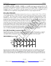
BASIC NETWORK CONNECTIONS Figure 25-1
TTIP
TRING
RTIP
RRING
DS21Q55
TRANSMIT
LINE
RECEIVE
LINE
1µF
60
60
0.01µF
BACKPLANE CONNECTIONS
1:1
2:1