


Product Preview DS21Q55
60 of 248 012103
Please contact telecom.support@dalsemi.com or search http://www.maxim-ic.com for updated
information.
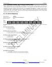
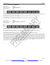
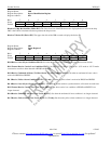
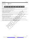
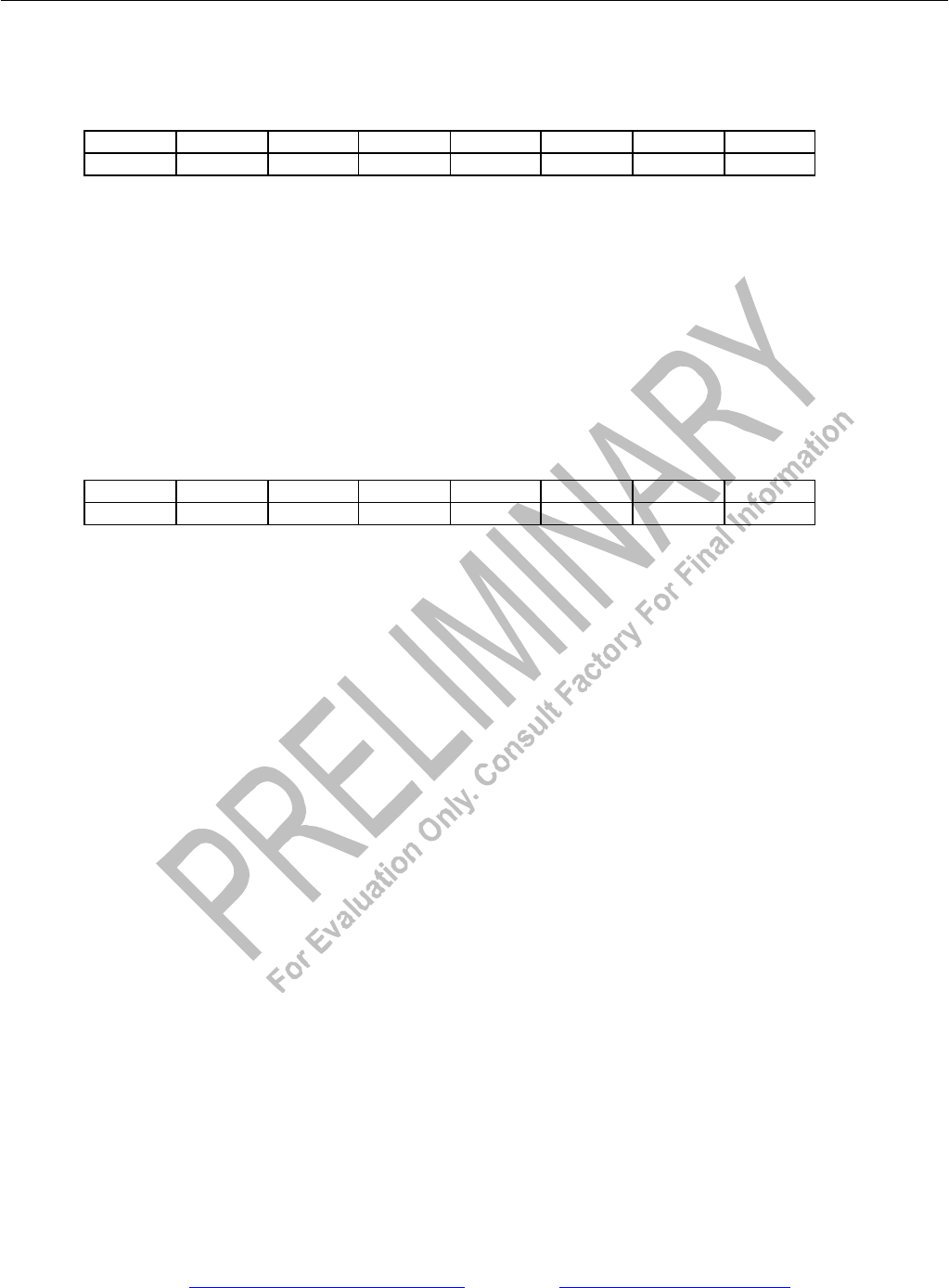
Register Name: IDR
Register Description: Device Identification Register
Register Address: 0Fh
Bit # 7 6 5 4 3 2 1 0
Name ID7 ID6 ID5 ID4 ID3 ID2 ID1 ID0
Default 1 0 1 1 X X X X
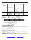
Bits 0 to 3/Chip Revision Bits (ID0 to ID3). The lower four bits of the IDR are used to display the die revision of the chip.
IDO is the LSB of a decimal code that represents the chip revision.
Bits 4 to 7/Device ID (ID4 to ID7). The upper four bits of the IDR are used to display the device ID.
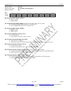
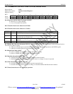
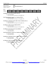
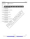
Register Name: SR2
Register Description: Status Register 2
Register Address: 18h
Bit # 7 6 5 4 3 2 1 0
Name RYELC RUA1C FRCLC RLOSC RYEL RUA1 FRCL RLOS
Default 0 0 0 0 0 0 0 0
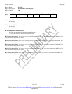
Bit 0/Receive Loss of Sync Condition (RLOS). Set when the device is not synchronized to the received data stream.
Bit 1/Framer Receive Carrier Loss Condition (FRCL). Set when 255 (or 2048 if E1RCR2.0 = 1) E1 mode or 192 T1 mode
consecutive zeros have been detected at RPOSI and RNEGI.
Bit 2/Receive Unframed All Ones (T1, Blue Alarm, E1, AIS) Condition (RUA1). Set when an unframed all ones code is
received at RPOSI and RNEGI.
Bit 3/Receive Yellow Alarm Condition (RYEL). (T1 only) Set when a yellow alarm is received at RPOSI and RNEGI.
Bit 4/Receive Loss of Sync Clear Event (RLOSC). Set when the framer achieves synchronization; will remain set until read.
Bit 5/Framer Receive Carrier Loss Clear Event (FRCLC). Set when carrier loss condition at RPOSI and RNEGI is no
longer detected.
Bit 6/Receive Unframed All Ones Clear Event (RUA1C). Set when the unframed all ones condition is no longer detected.
Bit 7/Receive Yellow Alarm Clear Event (RYELC). (T1 only) Set when the yellow alarm condition is no longer detected.