


Product Preview DS21Q55
53 of 248 012103
Please contact telecom.support@dalsemi.com or search http://www.maxim-ic.com for updated
information.
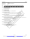
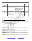
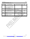
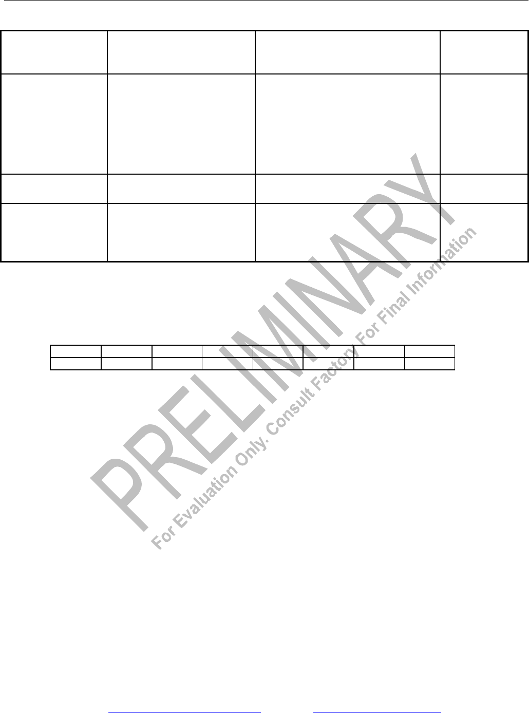
E1 SYNC/RESYNC CRITERIA Table 11-1
FRAME OR
MULTIFRAME
LEVEL
SYNC CRITERIA RESYNC CRITERIA ITU SPEC.
FAS FAS present in frame N
and N + 2, and FAS not
present in frame N + 1
Three consecutive incorrect FAS
received
Alternate: (E1RCR1.2 = 1) The
above criteria is met or three
consecutive incorrect bit 2 of non-
FAS received
G.706
4.1.1
4.1.2
CRC4 Two valid MF alignment
words found within 8ms
915 or more CRC4 code words out
of 1000 received in error
G.706
4.2 and 4.3.2
CAS Valid MF alignment word
found and previous
timeslot 16 contains code
other than all zeros
Two consecutive MF alignment
words received in error
G.732 5.2
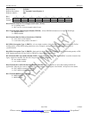
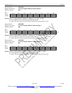
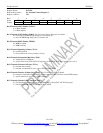
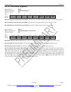
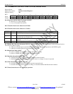
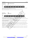
Register Name: E1RCR2
Register Description: E1 Receive Control Register 2
Register Address: 34h
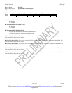
Bit # 7 6 5 4 3 2 1 0
Name Sa8S Sa7S Sa6S Sa5S Sa4S - - RCLA
Default 0 0 0 0 0 0 0 0
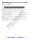
Bit 0/Receive Carrier Loss (RCL) Alternate Criteria (RCLA). Defines the criteria for a Receive Carrier Loss condition
for both the framer and Line Interface (LIU)
0 = RCL declared upon 255 consecutive zeros (125µs)
1 = RCL declared upon 2048 consecutive zeros (1ms)
Bit 1/Unused, must be set to zero for proper operation.
Bit 2/Unused, must be set to zero for proper operation.
Bit 3/Sa4-Bit Select(Sa4S). Set to one to have RLCLK pulse at the Sa4-bit position; set to zero to force RLCLK low during
Sa4-bit position. See Functional Timing Diagrams for details.
Bit 4/Sa5-Bit Select(Sa5S). Set to one to have RLCLK pulse at the Sa5-bit position; set to zero to force RLCLK low during
Sa5-bit position. See Functional Timing Diagrams for details.
Bit 5/Sa6-Bit Select(Sa6S). Set to one to have RLCLK pulse at the Sa6-bit position; set to zero to force RLCLK low during
Sa6-bit position. See Functional Timing Diagrams for details.
Bit 6/Sa7-Bit Select(Sa7S). Set to one to have RLCLK pulse at the Sa7-bit position; set to zero to force RLCLK low during
Sa7-bit position. See Functional Timing Diagrams for details.
Bit 7/Sa8-Bit Select (Sa8S). Set to one to have RLCLK pulse at the Sa8-bit position; set to zero to force RLCLK low during
Sa8-bit position. See Functional Timing Diagrams for details.