


Product Preview DS21Q55
186 of 248 012103
Please contact telecom.support@dalsemi.com or search http://www.maxim-ic.com for updated
information.
26. PAYLOAD ERROR INSERTION FUNCTION
An error-insertion function is available in the DS21Q55 and is used to create errors in the payload portion
of the T1 frame in the transmit path. Errors can be inserted over the entire frame or on a per-channel
basis. The user can select all DS0s or any combination of DS0s. See Special Per-Channel Registration
Operation for information on using the per-channel function. Errors are created by inverting the last bit in
the count sequence. For example, if the error rate 1 in 16 is selected, the 16
th
bit is inverted. F-bits are
excluded from the count and are never corrupted. Error rate changes occur on frame boundaries. Error-
insertion options include continuous and absolute number with both options supporting selectable-
insertion rates.
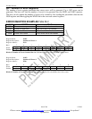
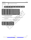
TRANSMIT ERROR INSERTION SETUP SEQUENCE Table 28-1
STEP ACTION
1 Enter desired error rate in the ERC register. Note: If ER3 through ER0 = 0,
no errors will be generated even if the constant error insertion feature is
enabled.
2A
or
2B
For constant error insertion set CE = 1 (ERC.4).
For a defined number of errors:
− Set CE = 0 (ERC.4)
− Load NOE1 and NOE2 with the number of errors to be inserted
− Toggle WNOE (ERC.7) from 0 to 1, to begin error insertion