


Product Preview DS21Q55
148 of 248 012103
Please contact telecom.support@dalsemi.com or search http://www.maxim-ic.com for updated
information.
22.5.2 Transmit Section
The transmit section will shift out into the T1 data stream, either the FDL (in the ESF framing mode) or
the Fs bits (in the D4 framing mode) contained in the transmit FDL register (TFDL). When a new value is
written to the TFDL, it will be multiplexed serially (LSB first) into the proper position in the outgoing T1
data stream. After the full eight bits has been shifted out, the framer will signal the host microcontroller
that the buffer is empty and that more data is needed by setting the SR8.2 bit to a one. The INT will also
toggle low if enabled via IMR8.2. The user has 2ms to update the TFDL with a new value. If the TFDL is
not updated, the old value in the TFDL will be transmitted once again. The framer also contains a zero
stuffer which is controlled via the T1TCR2.5 bit. In both ANSI T1.403 and TR54016, communications on
the FDL follows a subset of a LAPD protocol. The LAPD protocol states that no more than five ones
should be transmitted in a row so that the data does not resemble an opening or closing flag (01111110)
or an abort signal (11111111). If enabled via T1TCR2.5, the framer will automatically look for 5 ones in
a row. If it finds such a pattern, it will automatically insert a zero after the five ones. The T1TCR2.5 bit
should always be set to a one when the framer is inserting the FDL.
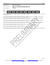
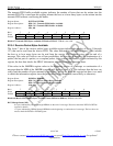
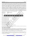
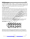
Register Name: TFDL
Register Description: Transmit FDL Register
Register Address: C1h
Bit # 7 6 5 4 3 2 1 0
Name TFDL7 TFDL6 TFDL5 TFDL4 TFDL3 TFDL2 TFDL1 TFDL0
Default 0 0 0 0 0 0 0 0
(Note: Also used to insert Fs framing pattern in D4 framing mode)
Bit 0/Transmit FDL Bit 0 (TFDL0). LSB of the Transmit FDL Code.
Bit 1/Transmit FDL Bit 1 (TFDL1).
Bit 2/Transmit FDL Bit 2 (TFDL2).
Bit 3/Transmit FDL Bit 3 (TFDL3).
Bit 4/Transmit FDL Bit 4 (TFDL4).
Bit 5/Transmit FDL Bit 5 (TFDL5).
Bit 6/Transmit FDL Bit 6 (TFDL6).
Bit 7/Transmit FDL Bit 7 (TFDL7). MSB of the Transmit FDL Code.
The transmit FDL Register (TFDL) contains the Facility Data Link (FDL) information that is to be inserted on a byte basis into
the outgoing T1 data stream. The LSB is transmitted first.
22.6 D4/SLC–96 Operation
In the D4 framing mode, the framer uses the TFDL register to insert the Fs framing pattern. To allow the
device to properly insert the Fs framing pattern, the TFDL register at address C1h must be programmed
to 1Ch and the following bits must be programmed as shown: T1TCR1.2 = 0 (source Fs data from the
TFDL register) T1TCR2.6 = 1 (allow the TFDL register to load on multiframe boundaries).
Since the SLC–96 message fields share the Fs-bit position, the user can access these message fields via
the TFDL and RFDL registers. Please see the separate application note for a detailed description of how
to implement a SLC–96 function.