


Product Preview DS21Q55
62 of 248 012103
Please contact telecom.support@dalsemi.com or search http://www.maxim-ic.com for updated
information.
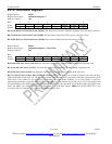
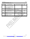
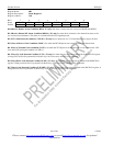
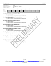
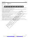
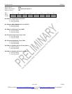
Register Name: SR3
Register Description: Status Register 3
Register Address: 1Ah
Bit # 7 6 5 4 3 2 1 0
Name LSPARE
LDN LUP LOTC LORC V52LNK
RDMA RRA
Default 0 0 0 0 0 0 0 0
Bit 0/Receive Remote Alarm Condition (RRA). (E1 only) Set when a remote alarm is received at RPOSI and RNEGI
Bit 1/Receive Distant MF Alarm Condition (RDMA). (E1 only) Set when bit 6 of timeslot 16 in frame 0 has been set for
two consecutive multiframes. This alarm is not disabled in the CCS signaling mode.
Bit 2/V5.2 Link Detected Condition (V52LNK). (E1 only) Set on detection of a V5.2 link identification signal. (G.965).
Bit 3/Loss of Receive Clock Condition (LORC). Set when the RCLKI pin has not transitioned for one channel time.
Bit 4/Loss of Transmit Clock Condition (LOTC). Set when the TCLK pin has not transitioned for one channel time. Will
force the LOTC pin high if enabled via CCR1.0.
Bit 5/Loop Up Code Detected Condition (LUP). (T1 only) Set when the loop up code as defined in the RUPCD1/2 register
is being received. See Programmable In-Band Loop Code Generation and Detection for details.
Bit 6/Loop Down Code Detected Condition (LDN). (T1 only) Set when the loop down code as defined in the RDNCD1/2
register is being received. See Programmable In-Band Loop Code Generation and Detection for details.
Bit 7/Spare Code Detected Condition (LSPARE). (T1 only) Set when the spare code as defined in the RSCD1/2 registers is
being received. See Programmable In-Band Loop Code Generation and Detection for details.