


Product Preview DS21Q55
70 of 248 012103
Please contact telecom.support@dalsemi.com or search http://www.maxim-ic.com for updated
information.
12.1 Per-Channel Loopback
The per-channel loopback registers (PCLRs) determine which channels (if any) from the backplane
should be replaced with the data from the receive side or in other words, off of the T1 or E1 line. If this
loopback is enabled, then transmit and receive clocks and frame syncs must be synchronized. One method
to accomplish this would be to tie RCLK to TCLK and RFSYNC to TSYNC. There are no restrictions on
which channels can be looped back or on how many channels can be looped back.
Each of the bit position in the PCLRs (PCLR1/PCLR2/PCLR3/PCLR4) represent a DS0 channel in the
outgoing frame. When these bits are set to a one, data from the corresponding receive channel will
replace the data on TSER for that channel.
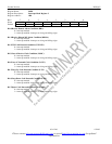
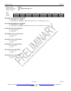
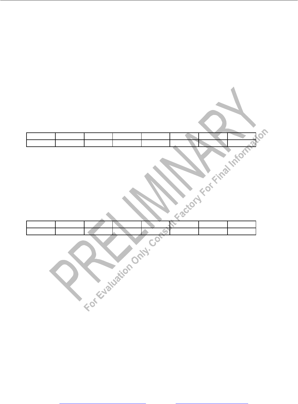
Register Name: PCLR1
Register Description: Per-Channel Loopback Enable Register 1
Register Address: 4Bh
Bit # 7 6 5 4 3 2 1 0
Name CH8 CH7 CH6 CH5 CH4 CH3 CH2 CH1
Default 0 0 0 0 0 0 0 0
Bits 0 to 7/Per-Channel Loopback Enable for Channels 1 to 8 (CH1 to CH8).
0 = loopback disabled
1 = enable loopback. Source data fro m the corresponding receive channel
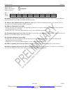
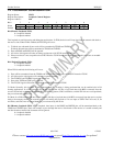
Register Name: PCLR2
Register Description: Per-Channel Loopback Enable Register 2
Register Address: 4Ch
Bit # 7 6 5 4 3 2 1 0
Name CH16 CH15 CH14 CH13 CH12 CH11 CH10 CH9
Default 0 0 0 0 0 0 0 0
Bits 0 to 7/Per-Channel Loopback Enable for Channels 9 to 16 (CH9 to CH16).
0 = loopback disabled
1 = enable loopback. Source data from the corresponding receive channel