


Product Preview DS21Q55
47 of 248 012103
Please contact telecom.support@dalsemi.com or search http://www.maxim-ic.com for updated
information.
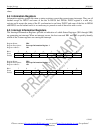
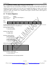
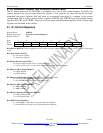
Register Name: T1CCR1
Register Description: T1 Common Control Register 1
Register Address: 07h
Bit # 7 6 5 4 3 2 1 0
Name - - - - - TFM PDE TLOOP
Default 0 0 0 0 0 0 0 0
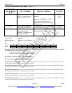
Bit 0/Transmit Loop Code Enable (TLOOP). See Programmable In-Band Loop Codes Generation and Detection for details.
0 = transmit data normally
1 = replace normal transmitted data with repeating code as defined in registers TCD1 and TCD2
Bit 1/Pulse Density Enforcer Enable (PDE). The framer always examines both the transmit and receive data streams for
violations of the following rules, which are required by ANSI T1.403: no more than 15 consecutive zeros and at least N ones
in each and every time window of 8 x (N +1) bits where N = 1 through 23. Violations for the transmit and receive data streams
are reported in the INFO1.6 and INFO1.7 bits respectively. When this bit is set to one, the device will force the transmitted
stream to meet this requirement no matter the content of the transmitted stream. When running B8ZS, this bit should be set to
zero since B8ZS encoded data streams cannot violate the pulse density requirements.
0 = disable transmit pulse density enforcer
1 = enable transmit pulse density enforcer
Bit 2/Transmit Frame Mode Select (TFM).
0 = D4 framing mode
1 = ESF framing mode
Bit 3/Unused, must be set to zero for proper operation.
Bit 4/Unused, must be set to zero for proper operation.
Bit 5/Unused, must be set to zero for proper operation.
Bit 6/Unused, must be set to zero for proper operation.
Bit 7/Unused, must be set to zero for proper operation.