


Product Preview DS21Q55
72 of 248 012103
Please contact telecom.support@dalsemi.com or search http://www.maxim-ic.com for updated
information.
13. ERROR COUNT REGISTERS
The DS21Q55 contains four counters that are used to accumulate line coding errors, path errors, and
synchronization errors. Counter update options include one second boundaries, 42ms (T1 mode only),
62ms (E1 mode only) or manually. See Error Counter Configuration Register (ERCNT). When updated
automatically, the user can use the interrupt from the timer to determine when to read these registers. All
four counters will saturate at their respective maximum counts and they will not rollover (Note: Only the
line-code violation-count register has the potential to overflow but the bit error would have to exceed
10E-2 before this would occur).
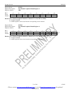
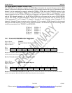
Register Name: ERCNT
Register Description: Error Counter Configuration Register
Register Address: 41h
Bit # 7 6 5 4 3 2 1 0
Name - MECU ECUS EAMS VCRFS FSBE MOSCRF LCVCRF
Default 0 0 0 0 0 0 0 0
Bit 0/T1 Line Code Violation Count Register Function Select (LCVCRF).
0 = do not count excessive zeros
1 = count excessive zeros
Bit 1/Multiframe Out of Sync Count Register Function Select (MOSCRF).
0 = count errors in the framing bit position
1 = count the number of multiframes out of sync
Bit 2/PCVCR Fs-Bit Error Report Enable (FSBE).
0 = do not report bit errors in Fs-bit position; only Ft-bit position
1 = report bit errors in Fs-bit position as well as Ft-bit position
Bit 3/E1 Line Code Violation Count Register Function Select (VCRFS).
0 = count BiPolar Violations (BPVs)
1 = count Code Violations (CVs)
Bit 4/Error Accumulation Mode Select (EAMS).
0 = ERCNT.5 determines accumu lation time
1 = ERCNT.6 determines accumulation time
Bit 5/Error Counter Update Select (ECUS).
T1 Mode: 0 = Update error counters once a second
1 = Update error counters every 42ms (333 frames)
E1 Mode: 0 = Update error counters once a second
1 = Update error counters every 62.5ms (500 frames)
Bit 6/Manual Error Counter Update (MECU). When enabled by ERCNT.4, the changing of this bit from a zero to a one
allows the next clock cycle to load the error counter registers with the latest counts and reset the counters. The user must wait a
minimum of 1.5 RCLK clock periods before reading the error count registers to allow for proper update.
Bit 7/Unused, must be set to zero for proper operation.