


Product Preview DS21Q55
46 of 248 012103
Please contact telecom.support@dalsemi.com or search http://www.maxim-ic.com for updated
information.
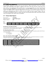
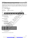
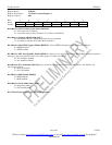
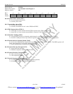
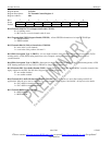
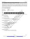
Register Name: T1TCR2
Register Description: T1 Transmit Control Register 2
Register Address: 06h
Bit # 7 6 5 4 3 2 1 0
Name TB8ZS TSLC96 TZSE FBCT2 FBCT1 TD4YM TZBTSI TB7ZS
Default 0 0 0 0 0 0 0 0
Bit 0/Transmit Side Bit 7 Zero Suppression Enable (TB7ZS).
0 = no stuffing occurs
1 = Bit 7 force to a one in channels with all zeros
Bit 1/Transmit Side ZBTSI Support Enable (TZBTSI). Allows ZBTSI information to be input on TLINK pin.
0 = ZBTSI disabled
1 = ZBTSI enabled
Bit 2/Transmit Side D4 Yellow Alarm Select (TD4YM).
0 = zeros in bit 2 of all channels
1 = a one in the S-bit position of frame 12
Bit 3/F-Bit Corruption Type 1. (FBCT1). A low-to-high transition of this bit causes the next three consecutive Ft (D4
framing mode) or FPS (ESF framing mode) bits to be corrupted, causing the remote end to experience a loss of
synchronization.
Bit 4/F-Bit Corruption Type 2. (FBCT2). Setting this bit high enables the corruption of one Ft (D4 framing mode) or FPS
(ESF framing mode) bit in every 128 Ft or FPS bits as long as the bit remains set.
Bit 5/Transmit FDL Zero Stuffer Enable (TZSE). Set this bit to zero if using the internal HDLC controller instead of the
legacy support for the FDL. See I/O Pin Configuration Options for details.
0 = zero stuffer disabled
1 = zero stuffer enabled
Bit 6/Transmit SLC–96/Fs-Bit Insertion Enable (TSLC96). Only set this bit to a one in D4 framing and SLC-96
applications. Must be set to one to source the Fs pattern from the TFDL register. See D4/SLC–96 Operation for details.
0 = SLC–96/Fs-bit insertion disabled
1 = SLC–96/Fs-bit insertion enabled
Bit 7/Transmit B8ZS Enable (TB8ZS).
0 = B8ZS disabled
1 = B8ZS enabled