


Product Preview DS21Q55
157 of 248 012103
Please contact telecom.support@dalsemi.com or search http://www.maxim-ic.com for updated
information.
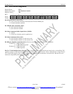
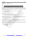
Register Name: LIC2
Register Description: Line Interface Control 2
Register Address: 79h
Bit # 7 6 5 4 3 2 1 0
Name ETS LIRST IBPV TUA1 JAMUX - SCLD CLDS
Default 0 0 0 0 0 0 0 0
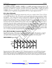
Bit 0 Custom Line Driver Select (CLDS). Setting this bit to a one will redefine the operation of the transmit line driver.
When this bit is set to a one and LIC1.5 = LIC1.6 = LIC1.7 = 0, then the device will generate a square wave at the TTIP and
TRING outputs instead of a normal waveform. When this bit is set to a one and LIC1.5 = LIC1.6 = LIC1.7 ≠ 0, then the device
will force TTIP and TRING outputs to become open-drain drivers instead of their normal push-pull operation. This bit should
be set to zero for normal operation of the device.
Bit 1/Short Circuit Limit Disable (ETS = 1) (SCLD). Controls the 50mA (rms) current limiter.
0 = enable 50mA current limiter
1 = disable 50mA current limiter
Bit 2/Unused, must be set to zero for proper operation.
Bit 3/Jitter Attenuator MUX (JAMUX). Controls the source for JACLK.
0 = JACLK sourced from MCLK (2.048MHz or 1.544MHz at MCLK)
1 = JACLK sourced from internal PLL (2.048MHz at MCLK)
Bit 4/Transmit Unframed All Ones (TUA1). The polarity of this bit is set such that the device will transmit an all ones
pattern on power-up or device reset. This bit must be set to a one to allow the device to transmit data. The transmission of this
data pattern is always timed off of the JACLK.
0 = transmit all ones at TTIP and TRING
1 = transmit data normally
Bit 5/Insert BPV (IBPV). A zero-to-one transition on this bit will cause a single BPV to be inserted into the transmit data
stream. Once this bit has been toggled from a zero to a one, the device waits for the next occurrence of three consecutive ones
to insert the BPV. This bit must be cleared and set again for a subsequent error to be inserted.
Bit 6/Line Interface Reset (LIRST). Setting this bit from a zero to a one will initiate an internal reset that resets the clock
recovery state machine and recenters the jitter attenuator. Normally this bit is only toggled on power-up. Must be cleared and
set again for a subsequent reset.
Bit 7/E1/T1 Select (ETS).
0 = T1 Mode Selected
1 = E1 Mode Selected