


Product Preview DS21Q55
187 of 248 012103
Please contact telecom.support@dalsemi.com or search http://www.maxim-ic.com for updated
information.
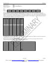
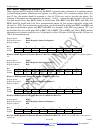
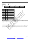
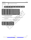
Register Name: ERC
Register Description: Error Rate Control Register
Register Address: EBh
Bit # 7 6 5 4 3 2 1 0
Name WNOE - - CE ER3 ER2 ER1 ER0
Default 0 0 0 0 0 0 0 0
Bits 0 to 3/Error Insertion Rate Select Bits (ER0 to ER3).
ER3 ER2 ER1 ER0 ERROR RATE
0 0 0 0 No errors inserted
0 0 0 1 1 in 16
0 0 1 0 1 in 32
0 0 1 1 1 in 64
0 1 0 0 1 in 128
0 1 0 1 1 in 256
0 1 1 0 1 in 512
0 1 1 1 1 in 1024
1 0 0 0 1 in 2048
1 0 0 1 1 in 4096
1 0 1 0 1 in 8192
1 0 1 1 1 in 16384
1 1 0 0 1 in 32768
1 1 0 1 1 in 65536
1 1 1 0 1 in 131072
1 1 1 1 1 in 262144
Bit 4/Constant Errors (CE). When this bit is set high (and the ER0 to ER3 bits are not set to 0000), the error insertion logic
will ignore the number of error registers (NOE1, NOE2) and generate errors constantly at the selected insertion rate. When CE
is set to zero, the NOEx registers determine how many errors are to be inserted.
Bit 5/Unused, must be set to zero for proper operation.
Bit 6/Unused, must be set to zero for proper operation.
Bit 7/Write NOE Registers (WNOE). If the host wishes to update to the NOEx registers, this bit must be toggled from a zero
to a one after the host has already loaded the prescribed error count into the NOEx registers. The toggling of this bit causes the
error count loaded into the NOEx registers to be loaded into the error insertion circuitry on the next clock cycle. Subsequent
updates require that the WNOE bit be set to zero and then one once again.