


Product Preview DS21Q55
63 of 248 012103
Please contact telecom.support@dalsemi.com or search http://www.maxim-ic.com for updated
information.
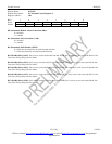
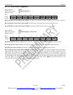
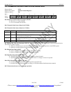
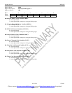
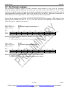
Register Name: IMR3
Register Description: Interrupt Mask Register 3
Register Address: 1Bh
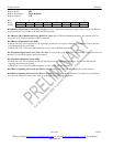
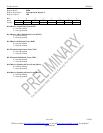
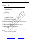
Bit # 7 6 5 4 3 2 1 0
Name LSPARE
LDN LUP LOTC LORC V52LNK
RDMA RRA
Default 0 0 0 0 0 0 0 0
Bit 0/Receive Remote Alarm Condition (RRA).
0 = interrupt masked
1 = interrupt enabled–interrupts on rising and falling edges
Bit 1/Receive Distant MF Alarm Condition (RDMA).
0 = interrupt masked
1 = interrupt enabled–interrupts on rising and falling edges
Bit 2/V5.2 Link Detected Condition (V52LNK).
0 = interrupt masked
1 = interrupt enabled–interrupts on rising and falling edges
Bit 3/Loss of Receive Clock Condition (LORC).
0 = interrupt masked
1 = interrupt enabled–interrupts on rising and falling edges
Bit 4/Loss of Transmit Clock Condition (LOTC).
0 = interrupt masked
1 = interrupt enabled–interrupts on rising and falling edges
Bit 5/Loop Up Code Detected Condition (LUP).
0 = interrupt masked
1 = interrupt enabled–interrupts on rising and falling edges
Bit 6/Loop Down Code Detected Condition (LDN).
0 = interrupt masked
1 = interrupt enabled–interrupts on rising and falling edges
Bit 7/Spare Code Detected Condition (LSPARE).
0 = interrupt masked
1 = interrupt enabled–interrupts on rising and falling edges