Product Preview DS21Q55
193 of 248 012103
Please contact telecom.support@dalsemi.com or search http://www.maxim-ic.com for updated
information.
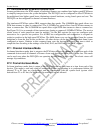
28. EXTENDED SYSTEM INFORMATION BUS (ESIB)
The ESIB allows two DS21Q55s to share an 8-bit CPU bus for the purpose of reporting alarms and
interrupt status as a group. With a single bus read, the host can be updated with alarm or interrupt status
from all members of the group. There are two control registers, ESIBCR1 and ESIBCR2, and four
information registers, ESIB1, ESIB2, ESIB3, and ESIB4. As an example, eight DS21Q55s can be
grouped into an ESIB group. A single read of the ESIB1 register of ANY member of the group will yield
the interrupt status of all eight DS21Q55s. Therefore the host can determine which device or devices are
causing an interrupt without polling all eight devices. Via ESIB2 the host can gather synchronization
status on all members of the group. ESIB3 and ESIB4 can be programmed to report various alarms on a
device by device basis.
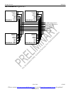
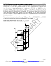
There are three device pins involved in forming a ESIB group. These are ESIBS0, ESIBS1, and ESIBRD.
A 10k pullup resistor must be provided on ESIBS0, ESIBS1, and ESIBRD.
ESIB GROUP OF FOUR DS21Q55s Figure 30-1
ESIB0
ESIB1
ESIBRD
CPU I/F
DS21Q55 # 1
ESIB0
ESIB1
ESIBRD
CPU I/F
DS21Q55 # 2
ESIB0
ESIB1
ESIBRD
CPU I/F
DS21Q55 # 3
ESIB0
ESIB1
ESIBRD
CPU I/F
DS21Q55 # 4
V
DD
10k (3)


