


Product Preview DS21Q55
21 of 248 012103
Please contact telecom.support@dalsemi.com or search http://www.maxim-ic.com for updated
information.
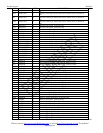
Signal Name: JTCLK
Signal Description: IEEE 1149.1 Test Clock Signal
Signal Type: Input
This signal is used to shift data into JTDI on the rising edge and out of JTDO on the falling edge.
Signal Name: JTDI
Signal Description: IEEE 1149.1 Test Data Input
Signal Type: Input
Test instructions and data are clocked into this pin on the rising edge of JTCLK. This pin has a 10k pullup resistor.
Signal Name: JTDO
Signal Description: IEEE 1149.1 Test Data Output
Signal Type: Output
Test instructions and data are clocked out of this pin on the falling edge of JTCLK. If not used, this pin should be left
unconnected.
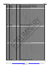
3.6 Line Interface Pins
Signal Name: MCLK1
Signal Description: Master Clock Input for Transceivers 1 & 2
Signal Type: Input
A (50ppm) clock source. This clock is used internally for both clock/data recovery and for the jitter attenuator for both T1 and
E1 modes. A quartz crystal of 2.048MHz can be applied across MCLK and XTALD instead of the clock source. The clock rate
can be 16.384MHz, 8.192MHz, 4.096MHz, or 2.048MHz. When using the DS21Q55 in T1-only operation a 1.544MHz
(50ppm) clock source can be used. MCLK1 and MCLK2 may be driven from a common clock.
Signal Name: MCLK2
Signal Description: Master Clock Input for Transceivers 3 & 4
Signal Type: Input
A (50ppm) clock source. This clock is used internally for both clock/data recovery and for the jitter attenuator for both T1 and
E1 modes. A quartz crystal of 2.048MHz can be applied across MCLK and XTALD instead of the clock source. The clock rate
can be 16.384MHz, 8.192MHz, 4.096MHz, or 2.048MHz. When using the DS21Q55 in T1-only operation a 1.544MHz
(50ppm) clock source can be used. MCLK1 and MCLK2 may be driven from a common clock.
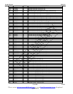
Signal Name: LIUC
Signal Description: Line Interface Connect
Signal Type: Input
Tie low to separate the line interface circuitry from the framer/formatter circuitry and activate the
TPOSI/TNEGI/TCLKI/RPOSI/RNEGI/RCLKI pins. Tie high to connect the line interface circuitry to the framer/formatter
circuitry and deactivate the TPOSI/TNEGI/TCLKI/RPOSI/RNEGI/RCLKI pins. When LIUC is tied high, the
TPOSI/TNEGI/TCLKI/ RPOSI/RNEGI/RCLKI pins should be tied low.
Signal Name: RTIPx and RRINGx
Signal Description: Receive Tip and Ring
Signal Type: Input
Analog inputs for clock recovery circuitry. These pins connect via a 1:1 transformer to the network. See Line Interface Unit for
details.