


Product Preview DS21Q55
39 of 248 012103
Please contact telecom.support@dalsemi.com or search http://www.maxim-ic.com for updated
information.
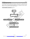
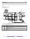
6.1 Power-Up Sequence
The DS21Q55 contains an on-chip power-up reset function, which automatically clears the writeable
register space immediately after power is supplied to the device. The user can issue a chip reset at any
time. Issuing a reset will disrupt traffic until the device is reprogrammed. The reset can be issued through
hardware using the TSTRST pin or through software using the SFTRST function in the master mode
register. The LIRST (LIC2.6) should be toggled from zero to one to reset the line interface circuitry. (It
will take the DS21Q55 about 40ms to recover from the LIRST bit being toggled.) Finally, after the
TSYSCLK and RSYSCLK inputs are stable, the receive and transmit elastic stores should be reset (this
step can be skipped if the elastic stores are disabled).
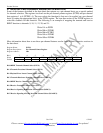
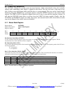
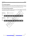
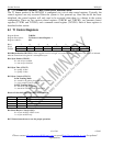
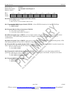
6.1.1 Master Mode Register
Register Name: MSTRREG
Register Description: Master Mode Register
Register Address: 00h
Bit # 7 6 5 4 3 2 1 0
Name - - - - TEST1 TEST0 T1/E1 SFTRST
Default 0 0 0 0 0 0 0 0
Bit 0/Software Issued Reset (SFTRST).
A 0 to 1 transition causes the register space to be cleared. A reset clears all configuration and status registers. The bit
automatically clears itself when the reset has completed.
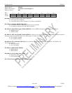
Bit 1/Operating Mode (T1/E1).
Used to select the operating mode of the framer/formatter (digital) portion of the 21Q55. The operating mode of the LIU must
also be programmed.
0 = T1 operation
1 = E1 operation
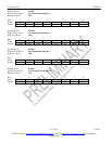
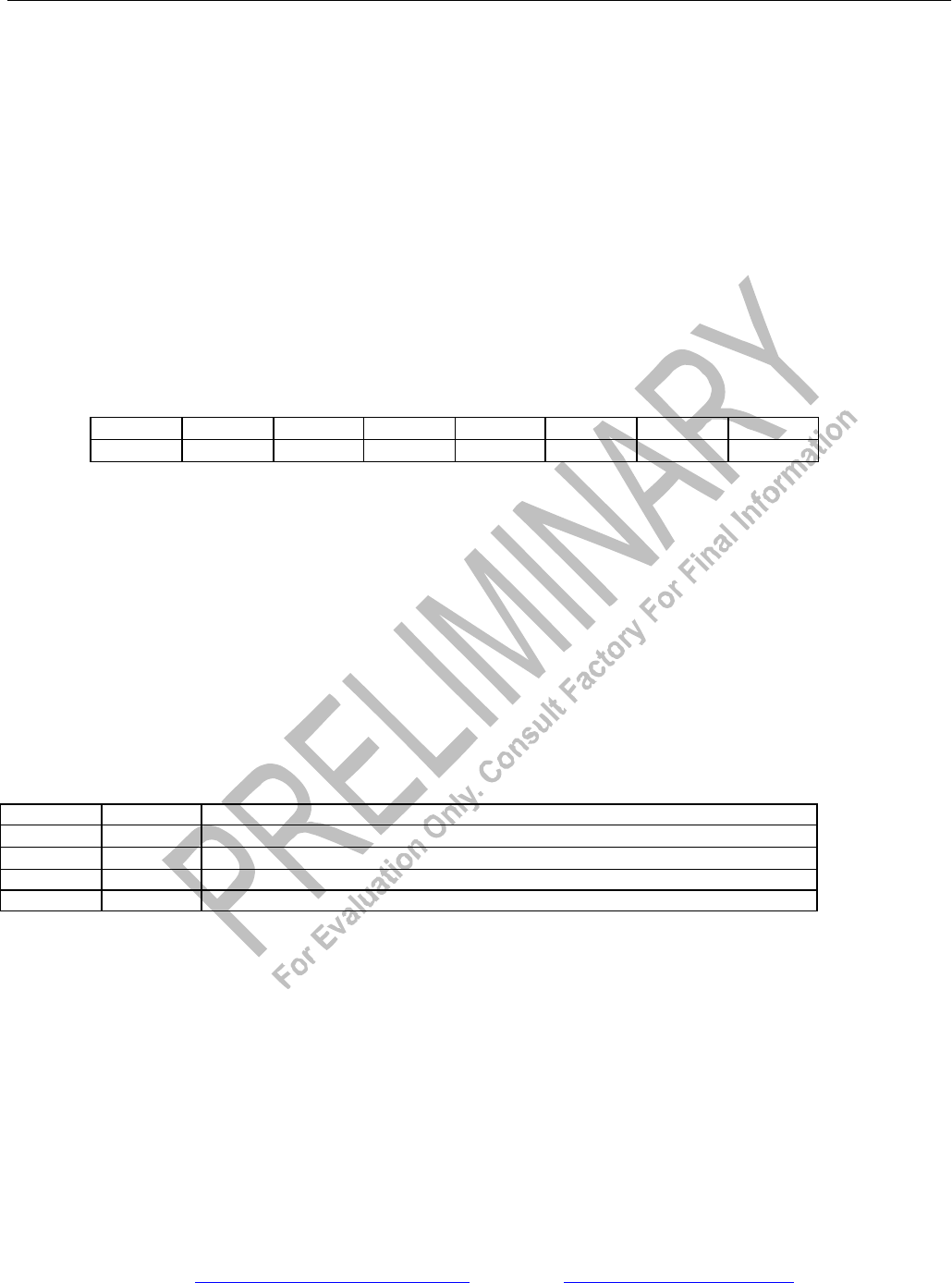
Bits 2, 3/Test Mode Bits (TEST0, TEST1).
Test modes are used to force the output pins of the 21Q55 into known states. This can facilitate the checkout of assemblies
during the manufacturing process and also be used to isolate devices from shared buses.
TEST1 TEST0 EFFECT ON OUTPUT PINS
0 0 Operate normally
0 1 Force all output pins into tristate (including all I/O pins and parallel port pins)
1 0 Force all output pins low (including all I/O pins except parallel port pins)
1 1 Force all output pins high (including all I/O pins except parallel port pins)
Bits 4–7/Unused, must be set to zero for proper operation.