


Product Preview DS21Q55
87 of 248 012103
Please contact telecom.support@dalsemi.com or search http://www.maxim-ic.com for updated
information.
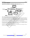
15.2 Transmit Signaling
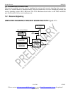
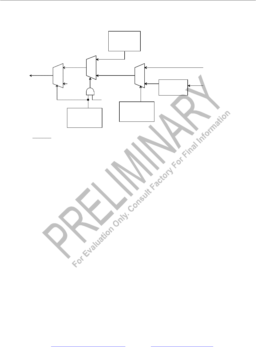
SIMPLIFIED DIAGRAM OF TRANSMIT SIGNALING PATH Figure 17-2
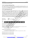
15.2.1 Processor-Based Transmit Signaling
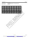
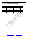
In processor-based mode, signaling data is loaded into the transmit-signaling registers (TS1–TS16) via
the host interface. On multiframe boundaries, the contents of these registers is loaded into a shift register
for placement in the appropriate bit position in the outgoing data stream. The user can utilize the transmit
multiframe interrupt in status register 4 (SR4.4) to know when to update the signaling bits. The user need
not update any transmit signaling register for which there is no change of state for that register.
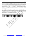
Each transmit signaling register contains the robbed-bit signaling (T1) or TS16 CAS signaling (E1) for
two timeslots that will be inserted into the outgoing stream if enabled to do so via T1TCR1.4 (T1 Mode)
or E1TCR1.6 (E1 Mode). In T1 mode, only TS1 through TS12 are used.
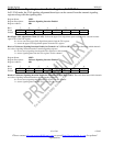
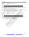
Signaling data can be sourced from the TS registers on a per-channel basis by utilizing the software-
signaling insertion-enable registers, SSIE1 through SSIE4.
TRANSMIT
SIGNALING
REGISTERS
SIGNALING
BUFFERS
PER-CHANNEL
CONTROL
TSER
TSIG
T1/E1 DATA
STREAM
PER-CHANNEL
CONTROL
SSIE1 - SSIE4
B7
T1TCR1.4
1
0
0
1
0
1
PCPR.3
ONLY APPLIES TO T1 MODE