


Product Preview DS21Q55
141 of 248 012103
Please contact telecom.support@dalsemi.com or search http://www.maxim-ic.com for updated
information.
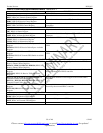
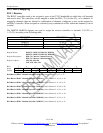
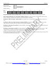
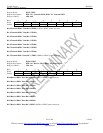
Register Name: SR6, SR7
Register Description: HDLC #1 Status Register 6
HDLC #2 Status Register 7
Register Address: 20h, 22h
Bit # 7 6 5 4 3 2 1 0
Name - TMEND RPE RPS RHWM RNE TLWM TNF
Default 0 0 0 0 0 0 0 0
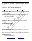
Bit 0/Transmit FIFO Not Full Condition (TNF). Set when the transmit 128-byte FIFO has at least one byte available.
Bit 1/Transmit FIFO Below Low Watermark Condition (TLWM). Set when the transmit 128-byte FIFO empties beyond
the low watermark as defined by the Transmit Low Watermark Register (TLWMR).
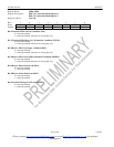
Bit 2/Receive FIFO Not Empty Condition (RNE). Set when the receive 128-byte FIFO has at least one byte available for a
read.
Bit 3/Receive FIFO Above High Watermark Condition (RHWM). Set when the receive 128-byte FIFO fills beyond the
high watermark as defined by the receive high-watermark register (RHWMR).
Bit 4/Receive Packet Start Event (RPS). Set when the HDLC controller detects an opening byte. This is a latched bit and will
be cleared when read.
Bit 5/Receive Packet End Event (RPE). Set when the HDLC controller detects either the finish of a valid message (i.e., CRC
check comp lete) or when the controller has experienced a message fault such as a CRC checking error, or an overrun
condition, or an abort has been seen. This is a latched bit and will be cleared when read.
Bit 6/Transmit Message End Event (TMEND). Set when the transmit HDLC controller has finished sending a message. This
is a latched bit and will be cleared when read.