


Product Preview DS21Q55
55 of 248 012103
Please contact telecom.support@dalsemi.com or search http://www.maxim-ic.com for updated
information.
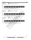
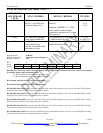
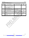
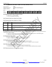
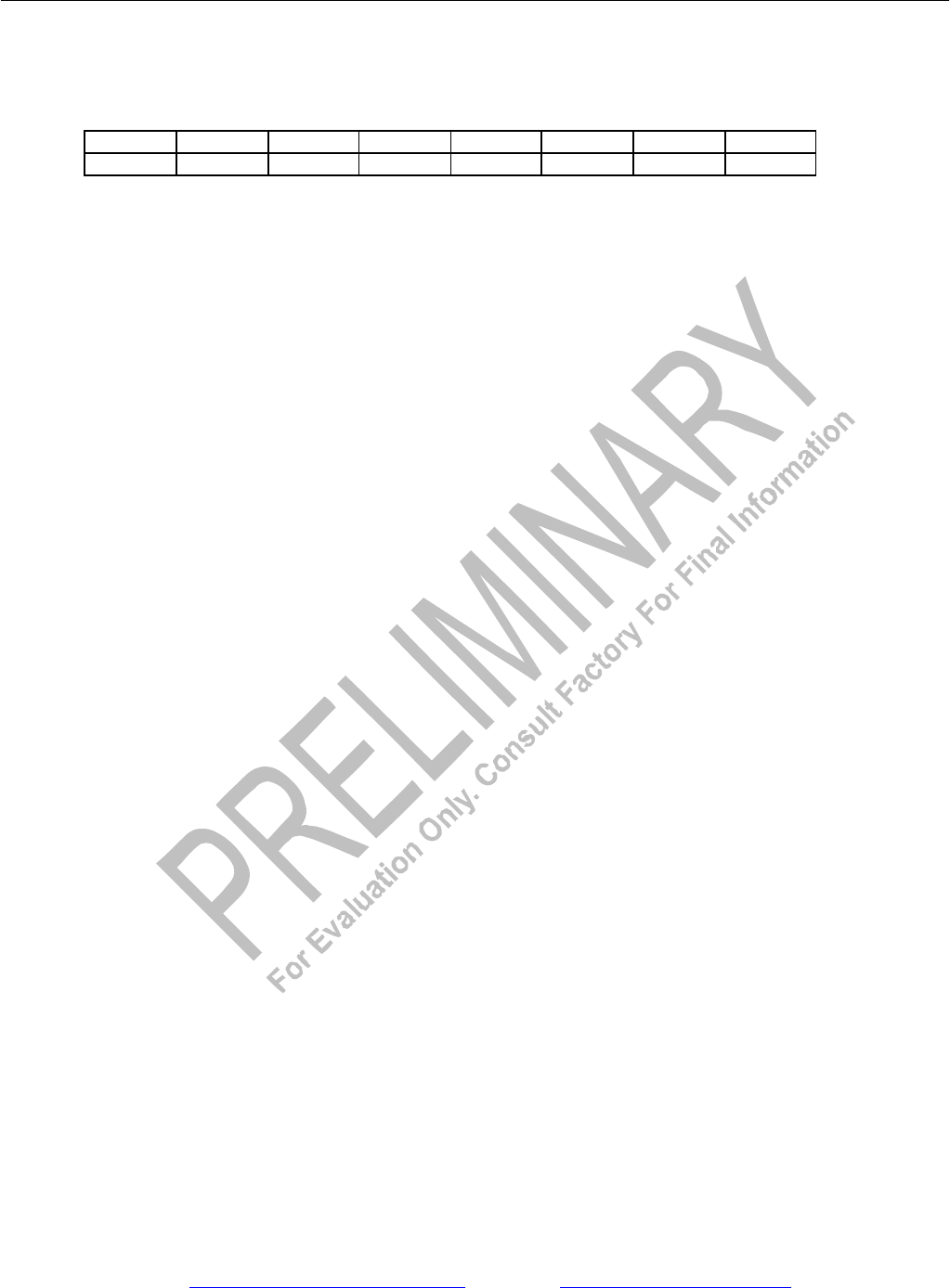
Register Name: E1TCR2
Register Description: E1 Transmit Control Register 2
Register Address: 36h
Bit # 7 6 5 4 3 2 1 0
Name Sa8S Sa7S Sa6S Sa5S Sa4S AEBE AAIS ARA
Default 0 0 0 0 0 0 0 0
Bit 0/Automatic Remote Alarm Generation (ARA).
0 = disabled
1 = enabled
Bit 1/Automatic AIS Generation (AAIS).
0 = disabled
1 = enabled
Bit 2/Automatic E-Bit Enable (AEBE).
0 = E-bits not automatically set in the transmit direction
1 = E-bits automatically set in the transmit direction
Bit 3/Sa4-Bit Select (Sa4S). Set to one to source the Sa4 bit from the TLINK pin; set to zero to not source the Sa4 bit. See
Functional Timing Diagrams for details.
Bit 4/Sa5-Bit Select (Sa5S). Set to one to source the Sa5 bit from the TLINK pin; set to zero to not source the Sa5 bit. See
Functional Timing Diagrams for details.
Bit 5/Sa6-Bit Select (Sa6S). Set to one to source the Sa6 bit from the TLINK pin; set to zero to not source the Sa6 bit. See
Functional Timing Diagrams for details.
Bit 6/Sa7-Bit Select (Sa7S). Set to one to source the Sa7 bit from the TLINK pin; set to zero to not source the Sa7 bit. See
Functional Timing Diagrams for details.
Bit 7/Sa8-Bit Select (Sa8S). Set to one to source the Sa8 bit from the TLINK pin; set to zero to not source the Sa8 bit. See
Functional Timing Diagrams for details.