


Product Preview DS21Q55
164 of 248 012103
Please contact telecom.support@dalsemi.com or search http://www.maxim-ic.com for updated
information.
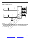
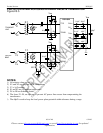
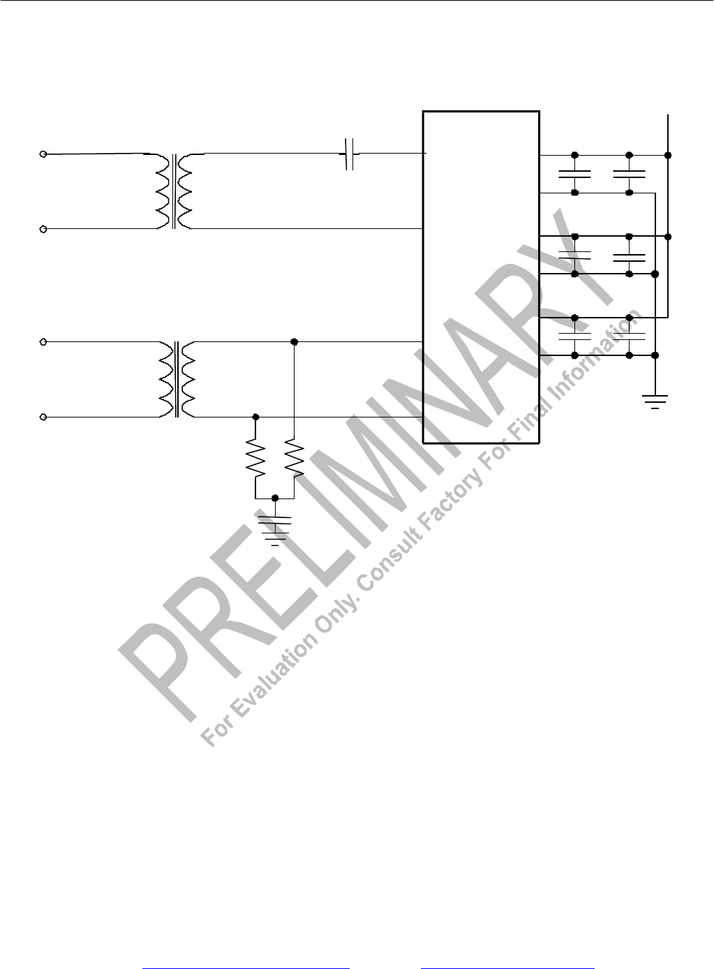
23.8 Recommended Circuits
BASIC INTERFACE Figure 25-4
NOTES:
1) All resistor values are ±1%.
2) Resistors R should be set to 60O each if the internal receive-side termination feature is enabled. When
this feature is disabled, R = 37.5O for 75O coaxial E1 lines, 60O for 120O twisted pair E1 lines, or
50O for 100O twisted pair T1 lines.
3) C = 1µF ceramic.
TTIP
TRING
RTIP
RRING
DV
DD
TV
DD
RV
DD
V
DD
DV
SS
TV
SS
RV
SS
DS21Q55
R
R
2:1
1:1
C
0.1µF
0.1µF
0.1µF
.01µF
TRANSMIT
LINE
RECEIVE
LINE
0.1µF
10µF
10µF
+
+