


2
Product checking and parts identification
1.1 Product checking and parts identification
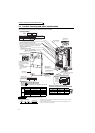
Unpack the inverter and check the capacity plate on the front cover and the rating plate on the inverter side face to
ensure that the product agrees with your order and the inverter is intact.
REMARKS
· For removal and reinstallation of covers, refer to page 6.
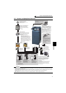
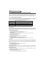
Rating plate example
The SERIAL consists of one symbol, two characters indicating production year and month, and six
characters indicating control number.
The last digit of the production year is indicated as the Year, and the Month is indicated by 1 to 9,
X (October), Y (November), or Z (December.)
Symbol Year Month Control number
SERIAL (Serial No.)
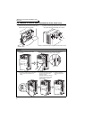
Operation panel (FR-DU07)
Front cover
EMC filter ON/OFF connector
Control circuit
terminal block
AU/PTC switchover switch
Main circuit
terminal block
Power lamp
Lit when the control circuit
(R1/L11, S1/L21) is supplied
with power.
Cooling fan
PU connector
RS-485 terminals
Connector for plug-in option connection
(Refer to the instruction manual of options.)
There are three connection connectors, and they are called
connector 1, connector 2, and connector 3 from the top.
Alarm lamp
Lit when the inverter is
in the alarm status
(Fault).
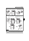
Capacity plate
Inverter model
Serial number
Capacity plate
Rating plate
USB connector
Voltage/current input switch
Charge lamp
Lit when power is supplied
to the main circuit
K
3.7
Represents inverter
capacity (kW)
FR-A720-3.7K
FR --A720
Symbol Voltage Class
A720
Three-phase 200V class
• Inverter Model
A740
Three-phase 400V class
Combed shaped
wiring cover
Rating plate
Inverter model
Input rating
Output rating
Serial number
Applied motor
capacity
FR-A720-3.7K
Production year and month
(Refer to page 27)
(Refer to page 68)
(Refer to page 15)
(Refer to page 16)
(Refer to page 431)
(Refer to page 330)
(Refer to page 25)
(Refer to the Instruction Manual (Applied).)
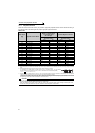
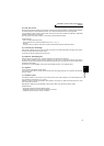
• Accessory
· Fan cover fixing screws (22K or lower)
(
Refer to
Instruction Manual (basic)
)
These screws are necessary for compliance with the EU
Directive.
Capacity Screw Size (mm) Quantity
200V
1.5K to 3.7K M3 × 35 1
5.5K to 11K M4 × 40 2
15K to 22K M4 × 50 1
400V
2.2K, 3.7K M3 × 35 1
5.5K to 15K M4 × 40 2
18.5K, 22K M4 × 50 1
(Refer to page 18)
(Refer to page 16)
(Refer to page 6)
(Refer to page 360)
(Refer to page 14)
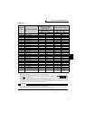
· DC reactor supplied (75K or higher)
· Eyebolt for hanging the inverter (30K to 280K)
Capacity Eyebolt Size Quantity
30K M8 2
37K to 132K M10 2
160K to 280K M12 2