


260
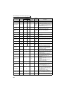
Monitor display and monitor output signal
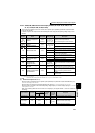
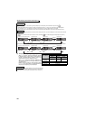
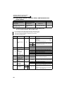
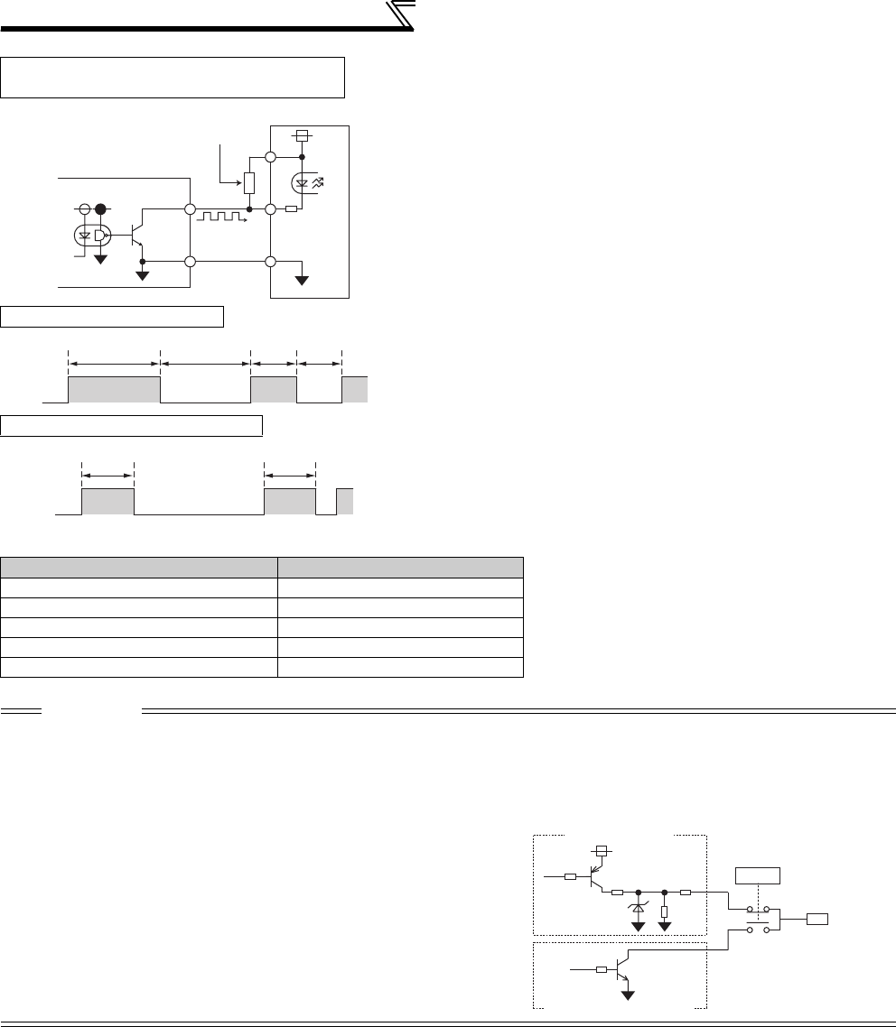
High speed pulse train output specifications
* The output pulse rate is 50kpps when a monitor output value is 100%.
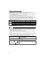
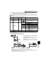
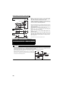
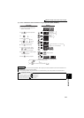
High speed pulse train output circuit
(connection example with a pulse counter)
• When Pr. 291 Pulse train I/O selection = "10, 11, 20, 21, 100",
high speed pulse train is output by open collector output.
Pulse train of maximum of 55k pulses/s is output.
Two types of pulse width, 50% Duty and fixed ON width, are
available. Adjustment by calibration parameter C0 (Pr. 900)
FM terminal calibration cannot be performed.
* When the output wiring length is long, a pulse shape is deformed due to the stray
capacitances of the wiring and output pulse cannot be recognized. If the wiring
length is long, connect the open collector output signal and the power supply using
an external pull up resistance.
Check specifications of a pulse counter for a resistance value to pull up. Select an
appropriate resistance value so that the load current is 80mA or less.
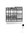
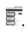
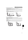
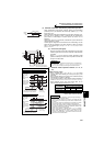
Pulse when Pr. 291 = "10, 11"
• When Pr. 291 = "10, 11", the pulse cycle is 50% Duty (ON
width and OFF width are the same).
• When Pr. 291 = "20, 21, 100", fixed ON width of pulse is out-
put (approx. 10µs).
• When the setting value is "100", the pulse train from the
pulse train input (terminal JOG) is output as is. Use this
value for synchronous speed operation of multiple inverters.
(Refer to page 378)
* Hi indicates that the open collector output transistor is ON.
Pulse when Pr. 291 = "20, 21, 100"
Item Specifications
Output method NPN open collector output
Voltage between a collector and emitter 30V (max)
Maximum permissible load current 80mA
Output pulse rate 0 to 55kpps
*
Output resolution 3pps (excluding a jitter)
CAUTION
⋅ Input specifications of terminal JOG (pulse train input or contact input) can be selected with Pr. 291.
Change the setting value using care not to change input specifications of terminal JOG. (Refer to page 378 for pulse train input.)
⋅ After changing a setting value of Pr. 291, connect a meter between terminal FM and SD. Take care that a voltage should not be
applied to terminal FM when FM output (voltage output) pulse train is selected.
⋅ The FM output of the inverter cannot be connected to devices which have source logic type pulse input.
⋅
When high speed pulse train output (Pr. 291 = "10, 11, 20, 21, 100") is
selected, performing parameter all clear returns the Pr. 291 setting to the
initial value of "0", changing the terminal FM output from high speed pulse
train output to FM output (voltage output).
FM
SD
Inverter
Pull up resistance *
Pulse counte
r
Hi * Low
50%duty
50%duty
Hi * Low
Approx. 10
μs
Approx. 10
μs
3.3kΩ
Terminal FM
0, 1
10, 11,
20, 21, 100
Pr.291
8.2V
FM output circuit
Open collector output circuit