


245
Function assignment of external terminal and control
4
PARAMETERS
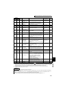
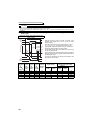
(5) Fault output signal (ALM, ALM2 signal)
(6) Input MC shutoff signal (Y91 signal)
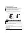
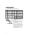
⋅ The Y91 signal is output at occurrence of a fault attributable to the failure of the inverter circuit or a fault caused by
a wiring mistake.
⋅ When using the Y91 signal, set "91 (positive logic)" or "191 (negative logic)" to any of Pr. 190 to Pr. 196 (output
terminal function selection) to assign the function to the output terminal.
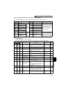
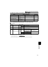
⋅ The following table indicates the faults that will output the Y91 signal. (Refer to page 404 for the fault description.)
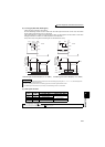
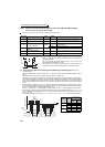
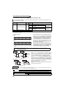
⋅ If the inverter comes to trip, the ALM and ALM2 signals are
output.
⋅ The ALM2 signal remains on during a reset period after fault
occurrence.
⋅ When using the ALM2 signal, set "94 (positive logic)" or "194
(negative logic)" to any of Pr. 190 to Pr. 196 (output terminal
function selection) to assign the function to the output
terminal.
⋅ The ALM signal is assigned to the A1B1C1 contact in the
initial setting.
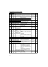
Fault Description
Inrush current limit circuit fault (E.IOH)
CPU fault (E.CPU)
CPU fault (E.5)
CPU fault (E.6)
CPU fault (E.7)
Parameter storage device fault (E.PE)
Parameter storage device fault (E.PE2)
24VDC power output short circuit (E.P24)
Operation panel power supply short circuit, RS-485 terminal
power supply short circuit (E.CTE)
Output side earth (ground) fault overcurrent protection (E.GF)
Output phase loss (E.LF)
Brake transistor alarm detection (E.BE)
♦ Parameters referred to ♦
Pr. 13 Starting frequency Refer to page 175
Pr. 76 Fault code output selection Refer to page 275
ON
OFF
ON
ON
OFF
Reset ON
Output frequency
ALM
A
LM2
RES
OFF
Inverter fault occurrence
(trip)
Reset processing
(about 1s)
Time
REMARKS
Refer to page 404 for the inverter fault description.