


16
Main circuit terminal specifications
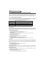
2.2 Main circuit terminal specifications
2.2.1 Specification of main circuit terminal
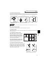
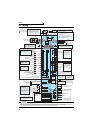
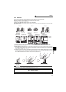
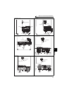
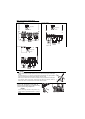
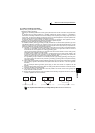
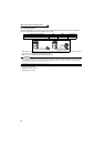
2.2.2 Terminal arrangement of the main circuit terminal, power supply and the motor
wiring.
Terminal
Symbol
Terminal Name Description
Refer
to
page
R/L1,
S/L2,
T/L3
AC power input
Connect to the commercial power supply.
Keep these terminals open when using the high power factor converter (FR-
HC and MT-HC) or power regeneration common converter (FR-CV).
—
U, V, W Inverter output Connect a three-phase squirrel-cage motor.
—
R1/L11,
S1/L21
Power supply for
control circuit
Connected to the AC power supply terminals R/L1 and S/L2. To retain the
fault display and fault output or when using the high power factor converter
(FR-HC and MT-HC) or power regeneration common converter (FR-CV),
remove the jumpers from terminals R/L1-R1/L11 and S/L2-S1/L21 and apply
external power to these terminals.
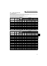
The power capacity necessary when separate power is supplied from R1/
L11 and S1/L21 differs according to the inverter capacity.
23
P/+, PR
Brake resistor
connection
(22K or lower)
Remove the jumper from terminals PR-PX (
7.5K
or lower) and connect an
optional brake resistor (FR-ABR) across terminals P/+-PR.
For the
22K
or lower, connecting the resistor further provides regenerative
braking power.
40
P/+, N/-
Brake unit
connection
Connect the brake unit (FR-BU2, FR-BU, BU and MT-BU5), power
regeneration common converter (FR-CV), power regeneration converter
(MT-RC), high power factor converter (FR-HC and MT-HC) or DC power
supply (under the DC feeding mode).
42
P/+, P1
DC reactor
connection
For the 55K or
lower
, remove the jumper across terminals P/+ - P1 and
connect the DC reactor. (As a DC reactor is supplied with the 75K or higher
as standard, be sure to connect the DC reactor.)
Keep the jumper across P/+ and P1 attached when a DC reactor is not
connected.
49
PR, PX
Built-in brake circuit
connection
When the jumper is connected across terminals PX-PR (initial status), the
built-in brake circuit is valid. (Provided for the 7.5K or
lower
.)
—
Earth (Ground) For earthing (grounding) the inverter chassis. Must be earthed (grounded).
21
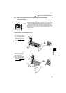
CAUTION
· When connecting a dedicated brake resistor (FR-ABR) and brake unit (FR-BU2, FR-BU, BU) remove jumpers across terminals
PR-PX (7.5K or lower). For details, refer to page 40.
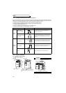
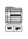
FR-A720-0.4K, 0.75K FR-A720-1.5K to 3.7K
FR-A740-0.4K to 3.7K
11K or lower 15K 18.5K or higher
200V class
60VA
80VA
80VA
400V class
60VA
60VA
80VA
R/L1
S/L2
T/L3
N/-
P/+
PR
PX
R1/L11
S1/L21
Charge lamp
Jumper
Jumper
Motor
Power supply
IM
R/L1 S/L2 T/L3
N/-
P/+
PR
PX
R1/L11 S1/L21
IM
Charge lamp
Jumper
Jumper
Motor
Power
supply