


318
Selection of operation mode and operation location
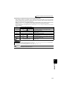
(8) Switchover mode (setting "6")
⋅ While continuing operation, you can switch among PU operation, External operation and Network operation (when
RS-485 terminals or communication option is used).
(9) PU operation interlock (setting "7")
⋅ The PU operation interlock function is designed to forcibly change the operation mode to External operation mode when
the PU operation interlock signal (X12) input turns OFF. This function prevents the inverter from being inoperative by
the external command if the mode is accidentally left unswitched from PU operation mode.
⋅ Set "7" (PU operation interlock) in Pr. 79.
⋅ For the terminal used for X12 signal (PU operation interlock signal) input, set "12" in any of Pr. 178 to Pr. 189 (input
terminal function selection) to assign the function. (Refer to page 231 for Pr. 178 to Pr. 189.)
⋅ When the X12 signal has not been assigned, the function of the MRS signal switches from MRS (output stop) to the
PU operation interlock signal.
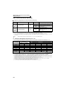
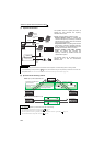
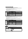
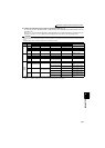
<Function/operation changed by switching ON/OFF the X12 (MRS) signal>
Operation Mode Switching
Switching Operation/Operating Status
External operation → PU
operation
Select the PU operation mode with the operation panel or parameter unit.
⋅ Rotation direction is the same as that of external operation.
⋅ The frequency set with the potentiometer (frequency setting command), etc. is used unchanged. (Note
that the setting will disappear when power is switched off or the inverter is reset.)
External operation → NET
operation
Send the mode change command to Network operation mode through communication.
⋅ Rotation direction is the same as that of external operation.
⋅ The value set with the setting potentiometer (frequency setting command) or like is used unchanged.
(Note that the setting will disappear when power is switched off or the inverter is reset.)
PU operation → external
operation
Press the external operation key of the operation panel, parameter unit.
⋅ The rotation direction is determined by the input signal of the external operation.
⋅ The set frequency is determined by the external frequency command signal.
PU operation → NET
operation
Send the mode change command to Network operation mode through communication.
⋅ Rotation direction and set frequency are the same as those of PU operation.
NET operation → external
operation
Send the mode change command to External operation mode through communication.
⋅ The rotation direction is determined by the input signal of the external operation.
⋅ The set frequency is determined by the external frequency command signal.
NET operation → PU
operation
Select the PU operation mode with the operation panel or parameter unit.
⋅
The rotation direction and frequency command in Network operation mode are used unchanged.
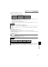
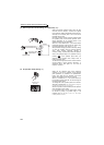
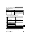
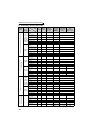
X12 (MRS)
signal
Function/Operation
Operation mode Parameter write
ON
Operation mode (external, PU, NET) switching
enabled
Output stop during external operation
Parameter write enabled (Pr. 77 Parameter write selection,
depending on the corresponding parameter write
condition (Refer to page 71 for the parameter list))
OFF
Forcibly switched to External operation mode
External operation allowed
Switching to the PU or NET operation mode from
the External operation mode is disabled.
Parameter write disabled with exception of Pr. 79
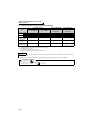
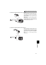
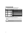
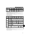
Operating Condition
X12 (MRS)
signal
Operation
Mode
Operating Status
Switching to
PU, NET
Operation Mode
Operation
mode
Status
PU/NET
During stop
ON→OFF
*1
External *2
If external operation frequency setting and start signal
are entered, operation is performed in that status.
Disallowed
Running
ON→OFF
*1
Disallowed
External
During stop
OFF→ON
External
*2
During stop
Allowed
ON→OFF Disallowed
Running
OFF→ON During operation → output stop Disallowed
ON→OFF Output stop → operation Disallowed
*1 The operation mode switches to External operation mode independently of whether the start signal (STF, STR) is ON or OFF. Therefore,
the motor is run in External operation mode when the X12 (MRS) signal is turned OFF with either of STF and STR is ON.
*2 At alarm occurrence, pressing on the operation panel resets the inverter.
CAUTION
⋅
If the X12 (MRS) signal is ON, the operation mode cannot be switched to PU operation mode when the start signal (STF, STR) is ON.
⋅ When the MRS signal is used as the PU interlock signal, the MRS signal serves as the normal MRS function (output stop) by
turning ON the MRS signal and then changing the Pr. 79 value to other than "7" in the PU operation mode. Also as soon as "7"
is set in Pr. 79, the signal acts as the PU interlock signal.
⋅ When the MRS signal is used as the PU operation interlock signal, the logic of the signal is as set in Pr. 17. When Pr. 17 = "2",
read ON as OFF and OFF as ON in the above explanation.
⋅ Changing the terminal assignment using Pr. 178 to Pr. 189 (input terminal function selection) may affect the other functions. Set
parameters after confirming the function of each terminal.