


140
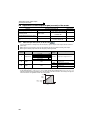
Position control by vector control
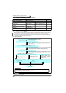
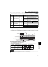
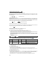
Relationship between position resolution Δ and overall accuracy
Since overall accuracy (positioning accuracy of machine) is the sum of electrical error and mechanical error, normally
take measures to prevent the electrical system error from affecting the overall error. As a guideline, refer to the
following relationship.
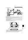
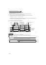
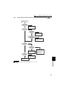
<Stopping characteristic of motor>
When parameters are used to run the motor, the internal command pulse frequency and motor speed have the
relationship as shown in the chart on page 133, and as the motor speed decreases, pulses are accumulated in the
deviation counter of the inverter. These pulses are called droop pulses (ε) and the relationship between command
frequency (fo) and position loop gain (Kp: Pr. 422) is as represented by the following expression.
When the initial value of Kp is 25s
-1
, the droop pulses (ε) are 8192 pulses.
Since the inverter has droop pulses during running, a stop settling time (ts) is needed from when the command has
zeroed until the motor stops. Set the operation pattern in consideration of the stop settling time.
When the initial value of Kp is 25s
-1
, the stop settling time (ts) is 0.12s.
The positioning accuracy Δε is (5 to 10) × Δ = Δε [mm]
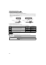
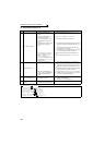
(2) Position command acceleration/deceleration time constant (Pr. 424 )
⋅ When the electronic gear ratio is large (about 10 or more times) and the speed is low, rotation will not be smooth,
resulting in pulse-wise rotation. At such a time, set this parameter to smooth the rotation.
⋅ When acceleration/deceleration time cannot be provided for the command pulses, a sudden change in command
pulse frequency may cause an overshoot or error excess alarm. At such a time, set this parameter to provide
acceleration/deceleration time.
Normally set 0.
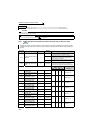
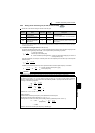
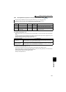
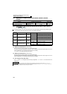
4.6.5 Setting of positioning adjustment parameter (Pr. 426, Pr. 427)
(1) In-position width (Pr. 426 )
The Y36 signal acts as an in-position signal.
When the number of droop pulses has fallen below the setting value, the in-position signal (Y36) turns ON.
For the Y36 signal, assign the function by setting "36" (positive logic) or "136" (negative logic) in any of Pr. 190 to Pr.
196 (output terminal function selection) .
(2) Excessive level error (Pr. 427 )
When droop pulses exceed the value set in Pr. 427 , excessive position error occurs and displays a fault (E.OD) to trip
the inverter. When you decreased the Pr. 422 Position loop gain setting, increase the error excessive level setting.
Also decrease the setting when you want to detect an error slightly earlier under large load.
When "9999" is set in Pr. 427 , excessive position error (E.OD) does not occur regardless of droop pulses.
Δ
<
(
1
to
1
)
×Δε Δε:positioning accuracy
510
ε =
fo
[pulse] ε =
204800
[pulse] (rated motor speed)
Kp 25
ts = 3 ×
1
[s]
Kp
♦Parameters referred to♦
Pr. 422 Position loop gain Refer to page 141
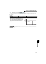
Parameter
Number
Name Initial Value Setting Range Description
426 In-position width 100 pulses
0 to 32767 pulses
*
When the number of droop pulses has fallen below the
setting value, the in-position signal (Y36) turns ON.
427 Excessive level error 40K
0 to 400K
Excessive position error (E.OD) occurs when the
number of droop pulses exceeds the setting.
9999 Function invalid
The above parameters can be set when the FR-A7AP/FR-A7AL (option) is mounted.
* When the operation panel (FR-DU07) is used, the maximum setting is 9999. When a parameter unit is used, up to the maximum value within
the setting range can be set.
Vector
Vector
Vector