


186
Selection and protection of a motor
(5) External thermal relay input (OH signal)
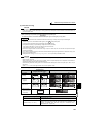
(6) PTC thermistor input (PTC signal)
Built-in PTC thermistor of the motor can be input to the PTC signal (AU terminal).
⋅ For the terminal used for PTC signal input, assign the function by setting "63" in Pr. 184 AU terminal function selection
and also set the AU/PTC switchover switch to the PTC terminal function. (The initial setting is the AU terminal
function.)
⋅ If a motor overheat state is detected for more than 10s according to the input from the PTC thermistor, the inverter
trips and outputs the PTC thermal fault signal (E.PTC).
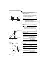
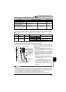
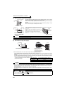
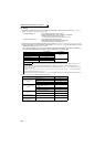
External thermal relay input
connection example
⋅ To protect the motor against overheat, use the OH signal when using an external
thermal relay or the built-in thermal protector of the motor.
⋅ When the thermal relay operates, the inverter trips and outputs the fault signal
(E.OHT).
⋅ For the terminal used for OH signal input, assign the function by setting "7" in any
of Pr. 178 to Pr. 189 (input terminal function selection)
⋅ A thermal protector is provided for a vector control dedicated motor (SF-V5RU).
* Assign OH (external thermal input) signal to the CS terminal.
(Pr. 186 = "7")
Connect a 2W1kΩ resistor between the terminal PC and
CS(OH).
Install the resistor pushing it against the bottom part of the
terminal block so as to avoid a contact with other cables.
Refer to
page 231 for details of Pr. 186 CS terminal function
selection.
CAUTION
⋅ Changing the terminal assignment using Pr. 178 to Pr. 189 (input terminal function selection) may affect the other functions. Set
parameters after confirming the function of each terminal.
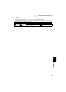
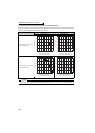
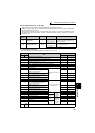
PTC thermistor input connection example
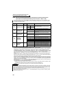
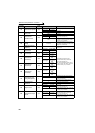
⋅ The input specifications of the PTC thermistor
are shown on the right.
Motor Temperature PTC Thermistor Resistance Value (Ω)
Normal 0 to 500
Boundary 500 to 4k
Overheat 4k or higher
CAUTION
⋅
When the PTC signal was not assigned to Pr. 184 and the AU/PTC switchover switch was set to the PTC terminal function, the
function assigned to the AU terminal is always OFF. Reversely, when the PTC signal was assigned to Pr. 184 and the AU/PTC
switchover switch was set to the AU terminal function, a PTC thermal fault (E.PTC) occurs since the function is always in a
motor overheat state.
⋅ When you want to input a current, assign the AU signal to the other signal.
⋅ When terminal assignment is changed, the other functions may be affected. Set parameter after confirming the function of the
AU terminal.
♦ Parameters referred to ♦
Pr. 71 Applied motor Refer to page 187
Pr. 72 PWM frequency selection Refer to page 284
Pr. 178 to Pr. 189 (input terminal function selection) Refer to page 231
Pr. 190 to Pr. 196 (output terminal function selection) Refer to page 239
Specifications of the AU terminal Refer to page 25
Inverter
U
V
W
OH
Thermal relay protecto
r
Motor
IM
SD
G1
G2
CS(OH)
SD
PC
2W1kΩ
Inverter
SF-V5RU
*
Connection of the thermal
protector of the SF-V5RU
CS(OH)
Resistor (2W1kΩ)
PC
Control circuit
terminal block
Inverter
U
AU
PTC
V
W
AU(PTC)
Moto
r
SD
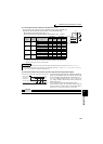
Inverter
AU/PTC switchover switch
AU
PTC
Factory-set to "AU".
Set to the "PTC" position to
validate the PTC signal input.