


130
Torque control by Real sensorless
vector control, vector control
4.5.6 Gain adjustment of torque control (Pr. 824, Pr. 825, Pr. 834, Pr. 835)
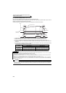
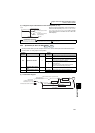
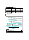
(1) Adjustment of current loop proportional (P) gain
⋅ For general adjustment, make setting within the range 50 to 200% as a guideline.
⋅ Set the proportional gain for torque control.
⋅ Increasing the value improves trackability in response to a current command change and reduces current variation
with disturbance. However, a too large gain will cause instability, generating harmonic torque pulsation.
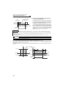
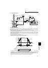
(2) Adjustment of current control integral time
⋅ Set the integral time of current control during torque control.
⋅ A small value enhances the torque response level, but a too small value will cause current fluctuation.
⋅ Decreasing the value shortens the time taken to return to the original torque if current variation with disturbance
occurs.
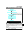
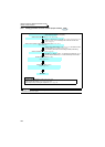
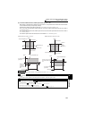
(3) Use multiple gains
⋅ When you want to change the gain according to applications, switch multiple motors with one inverter, etc., use
Torque control P gain 2 and Torque control integral time 2 .
⋅ Pr. 834 Torque control P gain 2 and Pr. 835 Torque control integral time 2 are valid when the RT signal is ON.
Although stable operation is possible with the initial value, make adjustment when any of such phenomena as
unusual motor and machine vibration/noise and overcurrent has occurred.
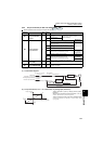
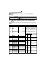
Parameter
Number
Name Initial Value
Setting
Range
Description
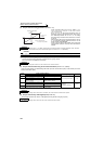
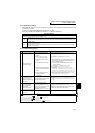
824 Torque control P gain 1
100% 0 to 200%
Set the current loop proportional gain.
100% is equivalent to 2000rad/s.
825
Torque control integral
time 1
5ms 0 to 500ms Set the current loop integral compensation time.
834 Torque control P gain 2
9999
0 to 200%
Set the current loop proportional gain when the RT
signal is ON.
9999 Without torque control P gain 2 function
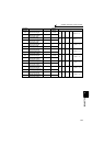
835
Torque control integral
time 2
9999
0 to500ms
Set the current loop integral compensation time when
the RT signal is ON.
9999 Without torque control integral time 2 function
REMARKS
⋅ The RT signal acts as the second function selection signal and makes the other second functions valid. (Refer to page 235.)
⋅ The RT signal is assigned to the terminal RT in the initial setting. By setting "3" in any of Pr. 178 to Pr. 189 (input terminal function
selection) , you can assign the RT signal to the other terminal.
Sensorless
Sensorless
Sensorless
Vector
Vector
Vector