


293
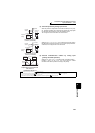
Frequency/torque setting by analog
input (terminal 1, 2, 4)
4
PARAMETERS
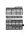
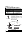
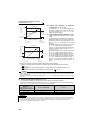
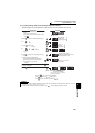
(2) Time constant of analog input (Pr. 74)
⋅ Effective for eliminating noise in the frequency setting circuit.
⋅ Increase the filter time constant if steady operation cannot be performed due to noise.
A larger setting results in slower response (The time constant can be set between approximately 5ms to 1s with the
setting of 0 to 8).
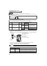
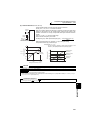
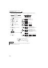
(3) Time constant of analog speed command input (Pr. 822, Pr. 832)
⋅ Set the time constant of the primary delay filter relative to the external torque command (analog input command)
using Pr. 822 Speed setting filter 1.
Set a large time constant when you want to delay the tracking of the speed command, when the analog input
voltage fluctuates, etc.
⋅ When you want to change time constant when switching two motors with one inverter, use the Pr. 832 Speed setting
filter 2.
⋅ Pr. 832 Speed setting filter 2 is valid when the RT signal turns ON.
(4) Time constant of analog torque command input (Pr. 826, Pr. 836)
⋅ Set the time constant of the primary delay filter relative to the external torque command (analog input command)
using Pr. 826 Torque setting filter 1.
Set a large time constant value when you want to delay the tracking of the torque command, when the analog input
voltage fluctuates, etc.
⋅ When you want to change time constant when switching two motors with one inverter, etc., use Pr. 836 Torque setting
filter 2.
⋅ Pr. 836 Torque setting filter 2 is valid when the RT signal turns ON.
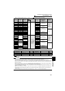
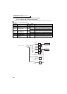
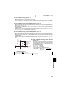
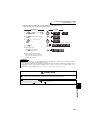
(5) Offset adjustment of analog speed command
input (Pr. 849)
⋅ When speed command by analog input is set, create the
range where the motor remains stop to prevent malfunction
at very low speed.
⋅ On the assumption that the Pr. 849 setting 100% as 0, the
offset voltage is offset as follows:
100% < Pr. 849 ........positive side
100% > Pr. 849 ........negative side
The offset voltage is found by the following formula.
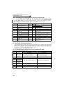
♦ Parameters referred to ♦
Pr. 73 Analog input selection Refer to page 286
Pr. 125, C2 to C4 (Bias and gain of the terminal 2 frequency setting) Refer to page 294
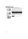
0% 100%
(10V or 5V)
Pr.849 setting
Frequency
command
Speed setting
signal
Slope determined
according to Pr.125
and C2 to C4
Slope does not
change.
0% 200%100%
* According to the Pr. 73 setting
Offset voltage =
Voltage at 100%
(5V or 10V *)
×
Pr. 849
− 100
[V]
100