


290
Frequency/torque setting by analog
input (terminal 1, 2, 4)
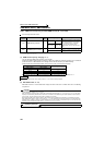
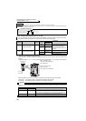
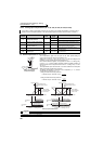
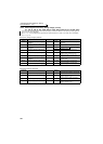
4.21.3 Analog input compensation (Pr. 73, Pr. 242, Pr. 243, Pr. 252, Pr. 253)
(1) Added compensation (Pr. 242, Pr. 243)
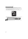
Auxiliary input characteristics
A fixed ratio of analog compensation (override) can be made by the added compensation or terminal 2 as an
auxiliary input for multi-speed operation or the speed setting signal (main speed) of the terminal 2 or terminal 4.
Parameter
Number
Name
Initial
Value
Setting
Range
Description
73 Analog input selection 1
0 to 3, 6, 7, 10
to 13, 16, 17
Added compensation
4, 5, 14, 15 Override compensation
242
Terminal 1 added compensation
amount (terminal 2)
100% 0 to 100%
Set the ratio of added compensation amount
when terminal 2 is the main speed.
243
Terminal 1 added compensation
amount (terminal 4)
75% 0 to 100%
Set the ratio of added compensation amount
when terminal 4 is the main speed.
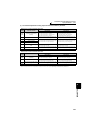
252 Override bias 50% 0 to 200%
Set the bias side compensation value of
override function.
253 Override gain 150% 0 to 200%
Set the gain side compensation value of
override function.
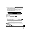
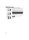
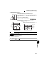
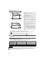
Added compensation
connection example
⋅ The compensation signal can be input for the main speed setting for
synchronous/continuous speed control operation, etc.
⋅ Setting any of "0 to 3, 6, 7, 10 to 13, 16, 17" in Pr. 73 adds the voltage across
terminals 1-5 to the voltage signal across terminals 2-5.
⋅ If the result of addition is negative, it is regarded as 0 at the Pr. 73 setting of any
of "0 to 3, 6, 7", or reverse rotation operation (polarity reversible operation) is
performed when the STF signal turns ON at the Pr. 73 setting of any of "10 to
13, 16, 17".
⋅ The compensation input of the terminal 1 can also be added to the multi-speed
setting or terminal 4 (initial value 4 to 20mA).
⋅ The added compensation for terminal 2 can be adjusted by Pr. 242, and the
compensation for terminal 4 by Pr. 243.
Analog command value using terminal 2
= Terminal 2 input + Terminal 1 input ×
Analog command value using terminal 4
= Terminal 4 input + Terminal 1 input ×
CAUTION
⋅ When the Pr. 73 setting was changed, check the voltage/current input switch setting. Different setting may cause a fault, failure
or malfunction. (Refer to page 286 for setting.)
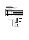
10
2
5
Forward
rotation
Inverter
STF
1
Auxiliary input
0 to 10V( 5V)
SD
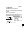
Pr. 242
100(%)
Pr. 243
100(%)
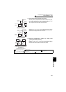
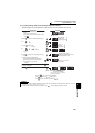
Output frequency
When voltage across
terminals 2 and 5 is 2.5V
(5V)
When voltage
across terminals
2 and 5 is 0V
+5V
(+10V)
Terminal 1
0
-2.5V
(-5V)
-5V
(-10V)
STF Signal
ON
STF Signal
ON
Forward rotation
Forward rotation
(a) When Pr. 73 setting is 0 to 5
Output frequency
When voltage across
terminals 2 and 5 is 2.5V
(5V)
When voltage
across terminals
2 and 5 is 0V
+5V
(+10V)
Terminal 1
0
-2.5V
(-5V)
-5V
(-10V)
Forward rotation
Forward rotation
(b) When Pr. 73 setting is 10 to 15
Reverse rotation
Reverse rotation
+2.5V
(+5V)
+2.5V
(+5V)
STF Signal
ON
STF Signal
ON