


49
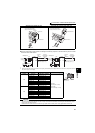
Connection of stand-alone option units
2
WIRING
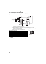
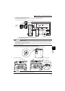
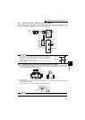
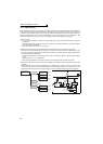
2.5.7 Connection of power regeneration converter (MT-RC)
When connecting a power regeneration converter (MT-RC), perform wiring securely as shown below. Incorrect
connection will damage the regeneration converter and inverter (75K or higher). After connecting securely, set "1" in Pr.
30 Regenerative function selection and "0" in Pr. 70 Special regenerative brake duty.
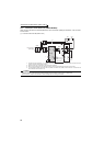
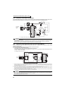
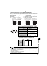
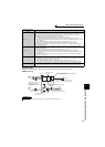
2.5.8 Connection of the power factor improving DC reactor (FR-HEL)
(1) Keep the surrounding air temperature within the permissible range (-10°C to +50°C). Keep enough clearance
around the reactor because it heats up. (Take 10cm or more clearance on top and bottom and 5cm or more on left
and right regardless of the installation direction.)
(2) When using the DC reactor (FR-HEL), connect it between terminals P1 and P/+.
For the 55K or lower, the jumper connected across terminals P1 and P/+ must be removed. Otherwise, the reactor
will not exhibit its performance.
For the 75K or higher, a DC reactor is supplied. Always install the reactor.
CAUTION
⋅ When using the FR-A700 series together with the MT-RC, install a magnetic
contactor (MC) at the input side of the inverter so that power is supplied to the
inverter after 1s or more has elapsed after powering ON the MT-RC. When power is
supplied to the inverter prior to the MT-RC, the inverter and the MT-RC may be
damaged or the MCCB may trip or be damaged.
⋅ Refer to the MT-RC manual for precautions for connecting the power coordination
reactor and others.
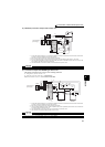
CAUTION
⋅ The wiring distance should be within 5m.
⋅
The size of the cables used should be equal to or larger than that of the power supply cables (R/L1, S/L2, T/L3).
(Refer to page 19)
DCL
P1
P1
R/L1
S/L2
T/L3
R1/L11
S1/L21
R
S
T
R
S
T
R1
S1
R2
S2
T2
R2
S2
T2
RES
STF
SD
C
B
A
U
V
W
Inverter
MT-RCL
P
P/+
N/-
PN
RDY
SE
MT-RC
Reset signal
Alarm signal
Ready signal
Three-phase
A
C power
supply
MCCB
MC2
IM
MC1
MT-RC power
supply (MC1)
Inverter input power
supply (MC2)
ON
ON
1s or more
5cm or more
5cm or more
10cm or more
5cm or more
5cm or more
P1
FR-HEL
Remove
the jumper.
P/+