


291
Frequency/torque setting by analog
input (terminal 1, 2, 4)
4
PARAMETERS
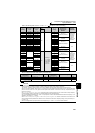
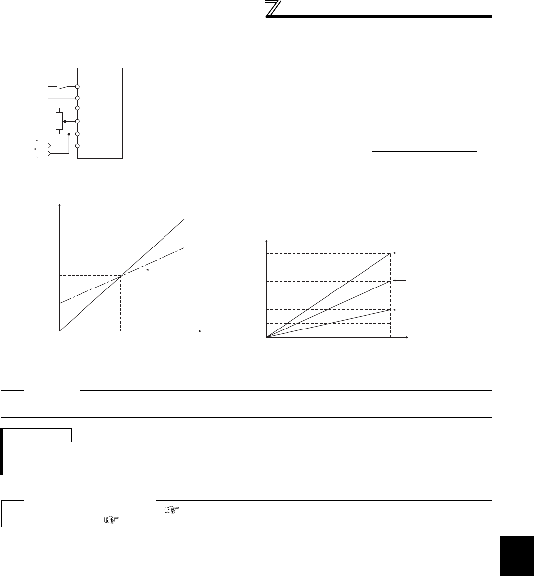
(2) Override function (Pr. 252, Pr. 253)
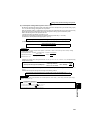
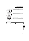
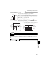
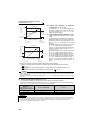
Override connection diagram
⋅ Use the override function to change the main speed at a fixed ratio.
⋅ Set any of "4, 5, 14, 15" in Pr. 73 to select an override.
⋅ When an override is selected, the terminal 1 or terminal 4 is used for the main speed
setting and the terminal 2 for the override signal. (When the main speed of the
terminal 1 or terminal 4 is not input, compensation made by the terminal 2 becomes
invalid.)
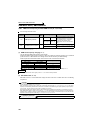
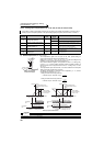
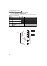
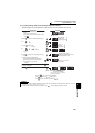
⋅ Using Pr. 252 and Pr. 253, set the override range.
⋅ How to find the set frequency for override
Set frequency (Hz) = Main speed set frequency (Hz) ×
Main speed set frequency (Hz): Terminal 1, 4 input, multi-speed setting
Compensation amount (%): Terminal 2 input
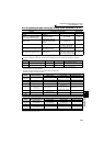
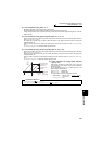
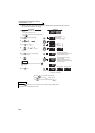
Example)When Pr. 73 = "5"
The set frequency changes as shown below according to the
terminal 1 (main speed) and terminal 2 (auxiliary) inputs.
CAUTION
⋅ When the Pr. 73 setting was changed, check the voltage/current input switch setting. Different setting may cause a fault, failure
or malfunction. (Refer to page 286 for setting.)
REMARKS
⋅ The AU signal must be turned ON to use the terminal 4.
⋅ When inputting compensation to multi-speed operation or remote setting, set "1" (compensation made) in Pr. 28 Multi-speed input
compensation selection. (Initial value is "0")
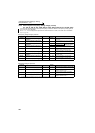
♦ Parameters referred to ♦
Pr. 28 Multi-speed input compensation selection Refer to page 169
Pr. 73 Analog input selection Refer to page 286
10
2
5
Forward
rotation
Main
speed
Inverter
STF
1
(-)
(+)
Override
setting
SD
Compensation amount (%)
100(%)
P
r.252
0V
2.5V
(5V)
5V
(10V)
0
50
100
150
200
Initial value
(50% to 150%)
Voltage across terminals 2 and 5
P
r.253
Override value (%)
0 2.5 5
0
Terminal 1 input voltage (V)
Set frequency (Hz)
Terminal 2 5VDC
input(150%)
Terminal 2 0V
input(50%)
Terminal 2 2.5VDC
input(100%)
30
15
60
45
90