


7
SPECIFICATIONS
459
Heatsink protrusion attachment
procedure
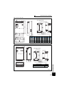
7.5 Heatsink protrusion attachment procedure
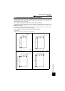
When encasing the inverter in an enclosure, the generated heat amount in an enclosure can be greatly reduced by
installing the heatsink portion of the inverter outside the enclosure. When installing the inverter in a compact enclosure,
etc., this installation method is recommended.
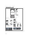
7.5.1 When using a heatsink protrusion attachment (FR-A7CN)
For the FR-A720-1.5K to 90K, FR-A740-0.4K to 132K, a heatsink can be protruded outside the enclosure using a
heatsink protrusion attachment (FR-A7CN). (For the FR-A740-160K or higher, attachment is not necessary when the
heatsink is to be protruded.)
For a panel cut dimension drawing and an installation procedure of the heatsink protrusion attachment (FR-A7CN) to
the inverter, refer to a manual of "heatsink protrusion attachment".
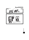
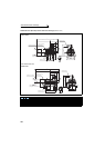
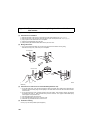
7.5.2 Protrusion of heatsink of the FR-A740-160K or higher
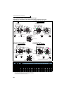
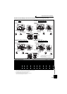
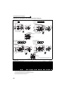
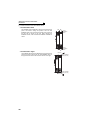
(1) Panel cutting
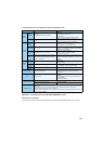
Cut the panel of the enclosure according to the inverter capacity.
• FR-A740-160K, 185K
Unit: mm
• FR-A740-220K, 250K, 280K
Unit: mm
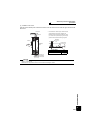
• FR-A740-315K, 355K
Unit: mm
• FR-A740-400K, 450K, 500K
Unit: mm
200 200
484
1395418
985
Hole
6-M10 screw
Hole
300 300
662
1595415
984
6-M10 screw
6-M10 screw
771
1300
21125821
Hole
315
315
8-M10 screw
300 300 300
976
21
150821
1550
Hole