


164
V/F pattern
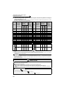
4.10.4 Adjustable 5 points V/F (Pr. 71, Pr. 100 to Pr. 109)
A dedicated V/F pattern can be made by freely setting the V/F characteristic between a startup and the base
frequency and base voltage under V/F control (frequency voltage/frequency).
The torque pattern that is optimum for the machine's characteristic can be set.
Parameter
Number
Name Initial Value Setting Range Description
71 Applied motor 0
0 to 8, 13 to 18,
20, 23, 24, 30, 33,
34, 40, 43, 44, 50,
53, 54
Set "2" for adjustable 5 points V/F
control.
100 V/F1(first frequency) 9999 0 to 400Hz, 9999
Set each points (frequency,
voltage) of V/F pattern.
9999: No V/F setting
101 V/F1(first frequency voltage) 0V 0 to 1000V
102 V/F2(second frequency) 9999 0 to 400Hz, 9999
103 V/F2(second frequency voltage) 0V 0 to 1000V
104 V/F3(third frequency) 9999 0 to 400Hz, 9999
105 V/F3(third frequency voltage) 0V 0 to 1000V
106 V/F4(fourth frequency) 9999 0 to 400Hz, 9999
107 V/F4(fourth frequency voltage) 0V 0 to 1000V
108 V/F5(fifth frequency) 9999 0 to 400Hz, 9999
109 V/F5(fifth frequency voltage) 0V 0 to 1000V
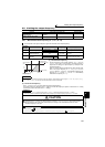
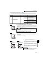
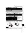
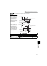
⋅ Any V/F characteristic can be provided by presetting the parameters of
V/F1 (first frequency voltage/first frequency) to V/F5.
⋅ For a machine of large static friction coefficient and small dynamic
static friction coefficient, for example, set a V/F pattern that will
increase the voltage only in a low-speed range since such a machine
requires large torque at a start.
(Setting procedure)
1)Set the rated motor voltage in Pr. 19 Base frequency voltage. (No
function at the setting of "9999" (initial value) or "8888".)
2)Set Pr. 71 Applied motor to "2" (Adjustable 5 points V/F characteristic).
3)Set the frequency and voltage you want to set in Pr. 100 to Pr. 109.
CAUTION
⋅
Adjustable 5 points V/F characteristics function only under V/F control. They do not function under Advanced magnetic flux
vector control, Real sensorless vector control or vector control.
⋅
When
Pr. 19 Base frequency voltage
= "8888" or "9999",
Pr. 71
cannot be set to "2". To set
Pr. 71
to "2", set the rated voltage value in
Pr. 19
.
⋅ When the frequency values at each point are the same, a write disable error ( ) appears.
⋅ Set the points (frequencies, voltages) of Pr. 100 to Pr. 109 within the ranges of Pr. 3 Base frequency and Pr. 19 Base frequency voltage.
⋅ When "2" is set in Pr. 71, Pr. 47 Second V/F (base frequency) and Pr. 113 Third V/F (base frequency) will not function.
⋅ When Pr. 71 is set to "2", the electronic thermal relay function makes calculation as a standard motor.
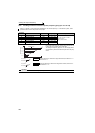
REMARKS
⋅
A greater energy saving effect can be expected by combining
Pr. 60 Energy saving control selection
and adjustable 5 points V/F.
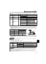
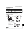
⋅ For the 5.5K, 7.5K, the Pr. 0 Torque boost and Pr. 12
DC injection brake operation voltage
settings are automatically changed
according to the Pr. 71 setting as follows.
♦ Parameters referred to ♦
⋅ Pr. 3 Base frequency, Pr. 19 Base frequency voltage Refer to page 159
⋅ Pr. 12 DC injection brake operation voltage Refer to page 203
⋅ Pr. 47 Second V/F (base frequency), Pr. 113 Third V/F (base frequency) Refer to page 159
⋅ Pr. 60 Energy saving control selection Refer to page 278
⋅ Pr. 71 Applied motor, Pr. 450 Second applied motor Refer to page 187
⋅ Advanced magnetic flux vector control Refer to page 148
⋅ Real sensorless vector control Refer to page 92
⋅ Vector control Refer to page 92
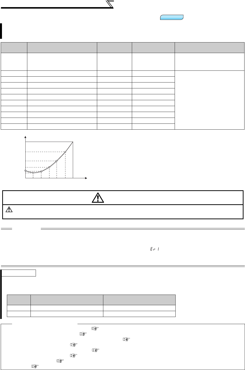
V/F
V/F
V/F
B
ase frequency
voltage
Pr.19
Base frequency
Pr.3
Torque boost
Pr.0
V/F Characteristic
0
V/F5
V/F4
V/F3
V/F2
V/F1
Frequency
Voltage
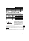
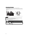
CAUTION
Make sure to set this parameter correctly according to the motor used.
Incorrect setting may cause the motor to overheat and burn.
Pr. 71
Standard Motor Setting
0, 2, 3 to 8, 20, 23, 24, 40, 43, 44
Constant Torque Motor Setting
1, 13 to 18, 50, 53, 54
Pr. 0 3% 2%
Pr. 12 4% 2%