


37
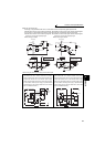
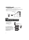
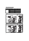
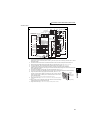
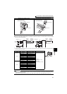
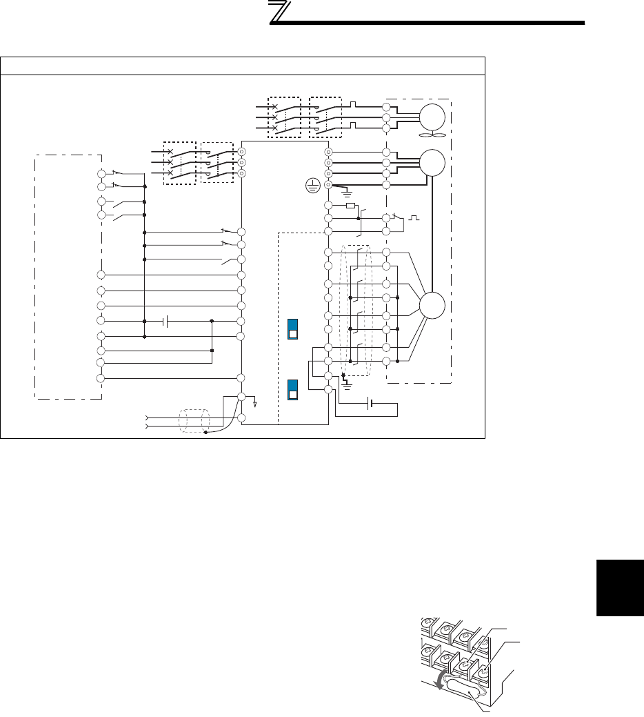
Connection of motor with encoder (vector control)
2
WIRING
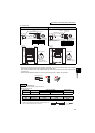
• Position control
Vector control dedicated motor (SF-V5RU, SF-THY), 12V complementary
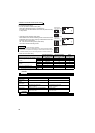
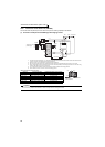
*1 The pin number differs according to the encoder used.
Speed control, torque control and position control by pulse train input could be normally performed with or without
connecting Z phase.
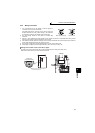
*2 Connect the encoder so that there is no looseness between the motor and motor shaft. Speed ratio should be 1:1.
*3 Earth (Ground) the shielded cable of the encoder cable to the enclosure with a P-clip, etc. (Refer to page 38.)
*4 For the complementary, set the terminating resistor selection switch to OFF position. (Refer to page 34.)
*5 A separate power supply of 5V/12V/15V/24V is necessary according to the encoder power specification.
Make the voltage of the external power supply the same as the encoder output voltage, and connect the external power
supply between PG and SD.
*6 For terminal compatibility of the FR-JCBL, FR-V7CBL and FR-A7AP, refer to page 36.
*7 For the fan of the 7.5kW or less dedicated motor, the power supply is single phase. (200V/50Hz, 200 to 230V/60Hz)
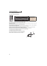
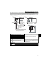
*8 Assign OH (external thermal input) signal to the terminal CS. (Set "7" in Pr. 186 )
Connect a 2W1kΩ resistor between the terminal PC and CS (OH). Install the
resistor pushing against the bottom part of the terminal block so as to avoid a
contact with other cables.
Refer to page 231 for details of Pr. 186 CS terminal function selection.
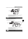
*9 Assign the function using Pr. 178 to Pr. 184, Pr. 187 to Pr. 189 (input terminal function
selection).
*10 When position control is selected, terminal JOG function is invalid and simple
position pulse train input terminal becomes valid.
*11 Assign the function using Pr. 190 to Pr. 194 (output terminal function selection).
SF-V5RU, SF-THY
A
B
C
G1
G2
FAN
*7
CS(OH)
SD
PC
2W1kΩ
Three-phase
AC power supply
Earth
(ground)
Thermal
protector
External thermal
relay input *8
MC OCR
MCCB
RDY
*11
NP *
9
CLR
*9
JOG
*10
LX *
9
1
5
(+)
(-)
R/L1
S/L2
T/L3
*4 *6
*3
PA1
FR-A7AP
PA2
PB1
PB2
PZ1
PZ2
Forward stroke end
Reverse stroke end
Pre-excitation/servo on
Clear signal
Pulse train
Sign signal
Preparation ready signal
STR
CLEAR
*1
OFF
U
V
W
U
V
W
E
A
*2
B
PA1
PA2
PB1
PB2
PZ1
PZ2
C
D
F
G
S
R
IM
Encoder
Inverter
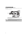
Positioning unit
MELSEQ-Q QD75P1
12VDC
power supply
(+)
(-)
*5
PULSE F
PULSE R
PULSE COM
CLEAR COM
RDY COM
READY
PC
SE
FLS
RLS
DOG
STOP
COM
24VDC power supply
Torque limit command
(
±
10V)
ON
Differential
line driver
Complementary
Terminating
resistor
PG
PG
SD
SD
MCCB
MC
Three-phase
AC power
supply
CS(OH)
Resistor (2W1kΩ)
PC
Control circuit
terminal block