


415
Causes and corrective actions
5
PROTECTIVE FUNCTIONS
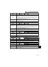
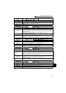
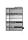
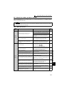
Operation Panel
Indication
E.OSD
FR-PU04
FR-PU07
E.OSd
Name
Speed deviation excess detection
Description
Trips the inverter if the motor speed is increased or decreased under the influence of the load etc.
during vector control with Pr. 285 Excessive speed deviation detection frequency set and cannot be
controlled in accordance with the speed command value.
This fault is not available in the initial status.
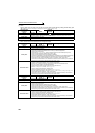
Check point
· Check that the values of Pr. 285 Excessive speed deviation detection frequency and Pr. 853 Speed deviation
time are correct.
· Check for sudden load change.
· Check that the number of encoder pulses does not differ from the actual number of encoder pulses.
Corrective action
·Set Pr. 285 Excessive speed deviation detection frequency and Pr. 853 Speed deviation time correctly.
· Keep load stable.
· Set the correct number of encoder pulses in Pr. 369 Number of encoder pulses.
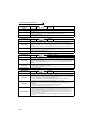
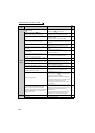
Operation Panel
Indication
E.ECT
FR-PU04
FR-PU07
E.ECT
Name
Signal loss detection
Description
Trips the inverter when the encoder signal is shut off under orientation control, encoder feedback
control or vector control.
This fault is not available in the initial status.
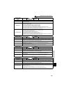
Check point
· Check for the encoder signal loss.
· Check that the encoder specifications are correct.
· Check for a loose connector.
· Check that the switch setting of FR-A7AP/FR-A7AL (option) is correct.
· Check that the power is supplied to the encoder. Or, check that the power is not supplied to the
encoder later than the inverter.
· Check that the voltage of the power supplied to the encoder is same as the encoder output voltage.
Corrective action
· Remedy the signal loss.
· Use an encoder that meets the specifications.
· Make connection securely.
· Make a switch setting of FR-A7AP/FR-A7AL (option) correctly. (Refer to page 34)
· Supply the power to the encoder. Or supply the power to the encoder at the same time when the
power is supplied to the inverter.
If the power is supplied to the encoder after the inverter, check that the encoder signal is securely
sent and set "0" in Pr. 376.
· Make the voltage of the power supplied to the encoder the same as the encoder output voltage.
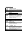
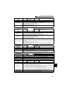
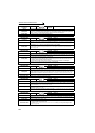
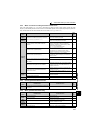
Operation Panel
Indication
E.OD
FR-PU04
FR-PU07
Fault 14
E.Od
Name
Excessive position fault
Description
Trips the inverter when the difference between the position command and position feedback exceeds
Pr. 427 Excessive level error under position control.
This fault is not available in the initial status.
Check point
· Check that the position detecting encoder mounting orientation matches the parameter.
· Check that the load is not large.
· Check that the Pr. 427 Excessive level error and Pr. 369 Number of encoder pulses are correct.
Corrective action
· Check the parameters.
· Reduce the load weight.
· Set the Pr. 427 Excessive level error and Pr. 369 Number of encoder pulses correctly.
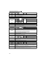
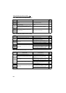
Operation Panel
Indication
E.EP
FR-PU04 Fault 14
FR-PU07 E.EP
Name
Encoder phase fault
Description
Trips the inverter when the rotation command of the inverter differs from the actual motor rotation
direction detected from the encoder.
This fault is not available in the initial status.
Check point
· Check for mis-wiring of the encoder cable.
· Check for wrong setting of Pr. 359 Encoder rotation direction.
Corrective action
· Perform connection and wiring securely.
· Change the Pr. 359 Encoder rotation direction value.